bolometer
Bolometer diagnostic
Maximum occurrences (MDS+ backend only): 2
New in version 3.7.4: lifecycle status alpha
Changed in version 4.2.0.
ids_propertiesstructure
See common IDS structure reference: ids_properties.
camera(i1)AoS¶Set of cameras
Set of cameras
Maximum occurrences (MDS+ backend only): 10
1 |
|
New in version 4.1.0.
camera(i1)/nameSTR_0D¶Short string identifier (unique for a given device)
Short string identifier (unique for a given device)
camera(i1)/descriptionSTR_0D¶Description, e.g. […]
Description, e.g. “Camera viewing the upper divertor”
New in version 4.0.0.
camera(i1)/typestructure¶Camera type
Camera type
This is an identifier. See camera_identifier for the available options.
camera(i1)/channel(i2)AoS¶Set of channels (detector or pixel of a camera)
Set of channels (detector or pixel of a camera)
Maximum occurrences (MDS+ backend only): 500
1 |
|
camera(i1)/channel(i2)/nameSTR_0D¶Short string identifier (unique for a given device)
Short string identifier (unique for a given device)
camera(i1)/channel(i2)/descriptionSTR_0D¶Description, e.g. […]
Description, e.g. “channel viewing the upper divertor”
New in version 4.0.0.
camera(i1)/channel(i2)/detectorstructure¶Detector description
Detector description
camera(i1)/channel(i2)/detector/geometry_typeINT_0D¶Type of geometry used to describe the surface of the detector […]
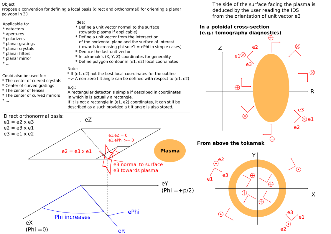
Type of geometry used to describe the surface of the detector or aperture (1:’outline’, 2:’circular’, 3:’rectangle’). In case of ‘outline’, the surface is described by an outline of point in a local coordinate system defined by a centre and three unit vectors X1, X2, X3. Note that there is some flexibility here and the data provider should choose the most convenient coordinate system for the object, respecting the definitions of (X1,X2,X3) indicated below. In case of ‘circular’, the surface is a circle defined by its centre, radius, and normal vector oriented towards the plasma X3. In case of ‘rectangle’, the surface is a rectangle defined by its centre, widths in the X1 and X2 directions, and normal vector oriented towards the plasma X3.
camera(i1)/channel(i2)/detector/centrestructure¶If geometry_type=2, coordinates of the centre of the circle. […]
If geometry_type=2, coordinates of the centre of the circle. If geometry_type=1 or 3, coordinates of the origin of the local coordinate system (X1,X2,X3) describing the plane detector/aperture. This origin is located within the detector/aperture area.
camera(i1)/channel(i2)/detector/radius ⇹mFLT_0D¶Radius of the circle, used only if geometry_type = 2
Radius of the circle, used only if geometry_type = 2
camera(i1)/channel(i2)/detector/x1_unit_vectorstructure¶Components of the X1 direction unit vector in the (X,Y,Z) coordinate […]
Components of the X1 direction unit vector in the (X,Y,Z) coordinate system, where X is the major radius axis for phi = 0, Y is the major radius axis for phi = pi/2, and Z is the height axis. The X1 vector is more horizontal than X2 (has a smaller abs(Z) component) and oriented in the positive phi direction (counter-clockwise when viewed from above).
Click here for further documentation.
camera(i1)/channel(i2)/detector/x1_unit_vector/x ⇹1FLT_0D¶Component along X axis
Component along X axis
camera(i1)/channel(i2)/detector/x2_unit_vectorstructure¶Components of the X2 direction unit vector in the (X,Y,Z) coordinate […]
Components of the X2 direction unit vector in the (X,Y,Z) coordinate system, where X is the major radius axis for phi = 0, Y is the major radius axis for phi = pi/2, and Z is the height axis. The X2 axis is orthonormal so that uX2 = uX3 x uX1.
Click here for further documentation.
camera(i1)/channel(i2)/detector/x2_unit_vector/x ⇹1FLT_0D¶Component along X axis
Component along X axis
camera(i1)/channel(i2)/detector/x3_unit_vectorstructure¶Components of the X3 direction unit vector in the (X,Y,Z) coordinate […]
Components of the X3 direction unit vector in the (X,Y,Z) coordinate system, where X is the major radius axis for phi = 0, Y is the major radius axis for phi = pi/2, and Z is the height axis. The X3 axis is normal to the detector/aperture plane and oriented towards the plasma.
Click here for further documentation.
camera(i1)/channel(i2)/detector/x3_unit_vector/x ⇹1FLT_0D¶Component along X axis
Component along X axis
camera(i1)/channel(i2)/detector/x1_width ⇹mFLT_0D¶Full width of the aperture in the X1 direction, used only if […]
Full width of the aperture in the X1 direction, used only if geometry_type = 3
camera(i1)/channel(i2)/detector/x2_width ⇹mFLT_0D¶Full width of the aperture in the X2 direction, used only if […]
Full width of the aperture in the X2 direction, used only if geometry_type = 3
camera(i1)/channel(i2)/detector/outlinestructure¶Irregular outline of the detector/aperture in the (X1, X2) coordinate […]
Irregular outline of the detector/aperture in the (X1, X2) coordinate system. Repeat the first point since this is a closed contour
Changed in version 4: Since this describes a closed countour first point must now be repeated at the end of the coordinate arrays of the children
camera(i1)/channel(i2)/detector/outline/x1(:) ⇹mFLT_1D¶Positions along x1 axis
Positions along x1 axis
1 |
|
camera(i1)/channel(i2)/aperture(i3)AoS¶Description of a set of collimating apertures
Description of a set of collimating apertures
Maximum occurrences (MDS+ backend only): 5
1 |
|
camera(i1)/channel(i2)/aperture(i3)/geometry_typeINT_0D¶Type of geometry used to describe the surface of the detector […]
Type of geometry used to describe the surface of the detector or aperture (1:’outline’, 2:’circular’, 3:’rectangle’). In case of ‘outline’, the surface is described by an outline of point in a local coordinate system defined by a centre and three unit vectors X1, X2, X3. Note that there is some flexibility here and the data provider should choose the most convenient coordinate system for the object, respecting the definitions of (X1,X2,X3) indicated below. In case of ‘circular’, the surface is a circle defined by its centre, radius, and normal vector oriented towards the plasma X3. In case of ‘rectangle’, the surface is a rectangle defined by its centre, widths in the X1 and X2 directions, and normal vector oriented towards the plasma X3.
camera(i1)/channel(i2)/aperture(i3)/centrestructure¶If geometry_type=2, coordinates of the centre of the circle. […]
If geometry_type=2, coordinates of the centre of the circle. If geometry_type=1 or 3, coordinates of the origin of the local coordinate system (X1,X2,X3) describing the plane detector/aperture. This origin is located within the detector/aperture area.
camera(i1)/channel(i2)/aperture(i3)/radius ⇹mFLT_0D¶Radius of the circle, used only if geometry_type = 2
Radius of the circle, used only if geometry_type = 2
camera(i1)/channel(i2)/aperture(i3)/x1_unit_vectorstructure¶Components of the X1 direction unit vector in the (X,Y,Z) coordinate […]
Components of the X1 direction unit vector in the (X,Y,Z) coordinate system, where X is the major radius axis for phi = 0, Y is the major radius axis for phi = pi/2, and Z is the height axis. The X1 vector is more horizontal than X2 (has a smaller abs(Z) component) and oriented in the positive phi direction (counter-clockwise when viewed from above).
Click here for further documentation.
camera(i1)/channel(i2)/aperture(i3)/x1_unit_vector/x ⇹1FLT_0D¶Component along X axis
Component along X axis
camera(i1)/channel(i2)/aperture(i3)/x2_unit_vectorstructure¶Components of the X2 direction unit vector in the (X,Y,Z) coordinate […]
Components of the X2 direction unit vector in the (X,Y,Z) coordinate system, where X is the major radius axis for phi = 0, Y is the major radius axis for phi = pi/2, and Z is the height axis. The X2 axis is orthonormal so that uX2 = uX3 x uX1.
Click here for further documentation.
camera(i1)/channel(i2)/aperture(i3)/x2_unit_vector/x ⇹1FLT_0D¶Component along X axis
Component along X axis
camera(i1)/channel(i2)/aperture(i3)/x3_unit_vectorstructure¶Components of the X3 direction unit vector in the (X,Y,Z) coordinate […]
Components of the X3 direction unit vector in the (X,Y,Z) coordinate system, where X is the major radius axis for phi = 0, Y is the major radius axis for phi = pi/2, and Z is the height axis. The X3 axis is normal to the detector/aperture plane and oriented towards the plasma.
Click here for further documentation.
camera(i1)/channel(i2)/aperture(i3)/x3_unit_vector/x ⇹1FLT_0D¶Component along X axis
Component along X axis
camera(i1)/channel(i2)/aperture(i3)/x1_width ⇹mFLT_0D¶Full width of the aperture in the X1 direction, used only if […]
Full width of the aperture in the X1 direction, used only if geometry_type = 3
camera(i1)/channel(i2)/aperture(i3)/x2_width ⇹mFLT_0D¶Full width of the aperture in the X2 direction, used only if […]
Full width of the aperture in the X2 direction, used only if geometry_type = 3
camera(i1)/channel(i2)/aperture(i3)/outlinestructure¶Irregular outline of the detector/aperture in the (X1, X2) coordinate […]
Irregular outline of the detector/aperture in the (X1, X2) coordinate system. Repeat the first point since this is a closed contour
Changed in version 4: Since this describes a closed countour first point must now be repeated at the end of the coordinate arrays of the children
camera(i1)/channel(i2)/aperture(i3)/outline/x1(:) ⇹mFLT_1D¶Positions along x1 axis
Positions along x1 axis
1 |
|
camera(i1)/channel(i2)/subcollimators_nINT_0D¶Number of sub-collimators
Number of sub-collimators
New in version 4.1.0.
camera(i1)/channel(i2)/subcollimators_separation ⇹mFLT_0D¶Thickness of separation between sub-collimators
Thickness of separation between sub-collimators
New in version 4.1.0.
camera(i1)/channel(i2)/etendue ⇹m^2.srFLT_0D¶Etendue (geometric extent) of the channel’s optical system
Etendue (geometric extent) of the channel’s optical system
camera(i1)/channel(i2)/etendue_methodstructure¶Method used to calculate the etendue. […]
Method used to calculate the etendue. Index = 0 : exact calculation with a 4D integral; 1 : approximation with first order formula (detector surface times solid angle subtended by the apertures); 2 : other methods
camera(i1)/channel(i2)/line_of_sightstructure¶Description of the reference line of sight of the channel, defined […]
Description of the reference line of sight of the channel, defined by two points when the beam is not reflected, a third point is added to define the reflected beam path
camera(i1)/channel(i2)/line_of_sight/first_pointstructure¶Position of the first point
Position of the first point
camera(i1)/channel(i2)/line_of_sight/second_pointstructure¶Position of the second point
Position of the second point
camera(i1)/channel(i2)/line_of_sight/third_pointstructure¶Position of the third point
Position of the third point
camera(i1)/channel(i2)/powerWstructure¶Power received on the detector
Power received on the detector
camera(i1)/channel(i2)/temperatureKstructure¶Temperature of detector foil
Temperature of detector foil
New in version 4.2.0.
camera(i1)/channel(i2)/validity_timedstructure¶Indicator of the validity of the channel as a function of time […]
Indicator of the validity of the channel as a function of time (0 means valid, negative values mean non-valid)
camera(i1)/channel(i2)/validityINT_0D¶Indicator of the validity of the channel for the whole acquisition […]
Indicator of the validity of the channel for the whole acquisition period (0 means valid, negative values mean non-valid)
camera(i1)/channel(i2)/ggd(itime)AoS¶Quantities based on GGD coordinates
Quantities based on GGD coordinates
1 |
camera(i1)/channel(i2)/ggd(itime)/geometry_matrixm^3structure¶Geometry matrix allowing to convert the power emitted by volume […]
Geometry matrix allowing to convert the power emitted by volume elements of the /ggd_grid into power measured by this channel. Power = sum_over ggd_volume_elements*geometry_matrix*emissivity
camera(i1)/channel(i2)/ggd(itime)/geometry_matrix/grid_indexINT_0D¶Index of the grid used to represent this quantity
Index of the grid used to represent this quantity
camera(i1)/channel(i2)/ggd(itime)/geometry_matrix/grid_subset_indexINT_0D¶Index of the grid subset the data is provided on. […]
Index of the grid subset the data is provided on. Corresponds to the index used in the grid subset definition: grid_subset(:)/identifier/index
camera(i1)/channel(i2)/ggd(itime)/geometry_matrix/values(:) ⇹m^3FLT_1D¶One scalar value is provided per element in the grid subset.
One scalar value is provided per element in the grid subset.
1 |
|
camera(i1)/channel(i2)/ggd(itime)/geometry_matrix/coefficients(:,:) ⇹m^3FLT_2D¶Interpolation coefficients, to be used for a high precision evaluation […]
Interpolation coefficients, to be used for a high precision evaluation of the physical quantity with finite elements, provided per element in the grid subset (first dimension).
1 |
|
2 |
|
power_radiated_total(:) ⇹WFLT_1D¶Total radiated power reconstructed from bolometry data
Total radiated power reconstructed from bolometry data
1 |
power_radiated_inside_lcfs(:) ⇹WFLT_1D¶Radiated power from the plasma inside the Last Closed Flux Surface, […]
Radiated power from the plasma inside the Last Closed Flux Surface, reconstructed from bolometry data
1 |
power_radiated_validity(:)INT_1D¶Validity flag related to the radiated power reconstructions
Validity flag related to the radiated power reconstructions
1 |
grid_typestructure¶Selection of one of a set of grid types for the 2D power density […]
Selection of one of a set of grid types for the 2D power density map
This is an identifier. See poloidal_plane_coordinates_identifier for the available options.
New in version 3.40.0.
gridstructure¶Definition of the 2D grid (the content of dim1 and dim2 is defined […]
Definition of the 2D grid (the content of dim1 and dim2 is defined by the selected grid_type)
New in version 3.40.0.
power_densityW.m^-3structure¶Power density map in the poloidal cross-section, obtained from […]
Power density map in the poloidal cross-section, obtained from tomographic inversion of the bolometer data
1 |
|
2 |
New in version 3.40.0.
grid_ggd(itime)AoS¶GGD grid. […]
GGD grid. The timebase of this array of structure must be a subset of the timebase on which physical quantities are described (camera/channel/ggd)
1 |
grid_ggd(itime)/identifierstructure¶Grid identifier
Grid identifier
This is an identifier. See ggd_identifier for the available options.
grid_ggd(itime)/pathSTR_0D¶Path of the grid, including the IDS name, in case of implicit […]
Path of the grid, including the IDS name, in case of implicit reference to a grid_ggd node described in another IDS. To be filled only if the grid is not described explicitly in this grid_ggd structure. Example syntax: #wall:2/description_ggd(1)/grid_ggd, means that the grid is located in the wall IDS, occurrence 2, with relative path description_ggd(1)/grid_ggd, using Fortran index convention (here : first index of the array)
grid_ggd(itime)/space(i1)AoS¶Set of grid spaces
Set of grid spaces
Click here for further documentation (or contact imas@iter.org if you can’t access this page).
1 |
|
grid_ggd(itime)/space(i1)/identifierstructure¶Space identifier
Space identifier
This is an identifier. See ggd_space_identifier for the available options.
grid_ggd(itime)/space(i1)/geometry_typestructure¶Type of space geometry (0: standard, 1:Fourier, >1: Fourier with […]
Type of space geometry (0: standard, 1:Fourier, >1: Fourier with periodicity)
grid_ggd(itime)/space(i1)/coordinates_type(i2)AoS¶Type of coordinates describing the physical space, for every […]
Type of coordinates describing the physical space, for every coordinate of the space. The size of this node therefore defines the dimension of the space.
This is an identifier. See coordinate_identifier for the available options.
1 |
|
Changed in version 4.0.0: Type changed from INT_1D
grid_ggd(itime)/space(i1)/coordinates_type(i2)/nameSTR_0D¶Short string identifier
Short string identifier
grid_ggd(itime)/space(i1)/objects_per_dimension(i2)AoS¶Definition of the space objects for every dimension (from one […]
Definition of the space objects for every dimension (from one to the dimension of the highest-dimensional objects). The index correspond to 1=nodes, 2=edges, 3=faces, 4=cells/volumes, …. For every index, a collection of objects of that dimension is described.
1 |
|
grid_ggd(itime)/space(i1)/objects_per_dimension(i2)/object(i3)AoS¶Set of objects for a given dimension
Set of objects for a given dimension
1 |
|
grid_ggd(itime)/space(i1)/objects_per_dimension(i2)/object(i3)/boundary(i4)AoS¶Set of (n-1)-dimensional objects defining the boundary of this […]
Set of (n-1)-dimensional objects defining the boundary of this n-dimensional object
1 |
|
grid_ggd(itime)/space(i1)/objects_per_dimension(i2)/object(i3)/boundary(i4)/indexINT_0D¶Index of this (n-1)-dimensional boundary object
Index of this (n-1)-dimensional boundary object
grid_ggd(itime)/space(i1)/objects_per_dimension(i2)/object(i3)/boundary(i4)/neighbours(:)INT_1D¶List of indices of the n-dimensional objects adjacent to the […]
List of indices of the n-dimensional objects adjacent to the given n-dimensional object. An object can possibly have multiple neighbours on a boundary
1 |
|
grid_ggd(itime)/space(i1)/objects_per_dimension(i2)/object(i3)/geometry(:)mixedFLT_1D¶Geometry data associated with the object, its detailed content […]
Geometry data associated with the object, its detailed content is defined by ../../geometry_content. Its dimension depends on the type of object, geometry and coordinate considered.
1 |
|
grid_ggd(itime)/space(i1)/objects_per_dimension(i2)/object(i3)/nodes(:)INT_1D¶List of nodes forming this object (indices to objects_per_dimension(1)%object(:) […]
List of nodes forming this object (indices to objects_per_dimension(1)%object(:) in Fortran notation)
1 |
|
grid_ggd(itime)/space(i1)/objects_per_dimension(i2)/object(i3)/measurem^dimensionFLT_0D¶Measure of the space object, i.e. […]
Measure of the space object, i.e. physical size (length for 1d, area for 2d, volume for 3d objects,…)
grid_ggd(itime)/space(i1)/objects_per_dimension(i2)/object(i3)/geometry_2d(:,:)mixedFLT_2D¶2D geometry data associated with the object. […]
2D geometry data associated with the object. Its dimension depends on the type of object, geometry and coordinate considered. Typically, the first dimension represents the object coordinates, while the second dimension would represent the values of the various degrees of freedom of the finite element attached to the object.
1 |
|
2 |
|
New in version 3.36.0.
grid_ggd(itime)/space(i1)/objects_per_dimension(i2)/geometry_contentstructure¶Content of the ../object/geometry node for this dimension
Content of the ../object/geometry node for this dimension
This is an identifier. See ggd_geometry_content_identifier for the available options.
New in version 3.34.0.
grid_ggd(itime)/space(i1)/objects_per_dimension(i2)/geometry_content/nameSTR_0D¶Short string identifier
Short string identifier
grid_ggd(itime)/grid_subset(i1)AoS¶Grid subsets
Grid subsets
1 |
|
grid_ggd(itime)/grid_subset(i1)/identifierstructure¶Grid subset identifier
Grid subset identifier
Click here for further documentation.

This is an identifier. See ggd_subset_identifier for the available options.
grid_ggd(itime)/grid_subset(i1)/identifier/nameSTR_0D¶Short string identifier
Short string identifier
grid_ggd(itime)/grid_subset(i1)/dimensionINT_0D¶Space dimension of the grid subset elements, using the convention […]
Space dimension of the grid subset elements, using the convention 1=nodes, 2=edges, 3=faces, 4=cells/volumes
grid_ggd(itime)/grid_subset(i1)/element(i2)AoS¶Set of elements defining the grid subset. […]
Set of elements defining the grid subset. An element is defined by a combination of objects from potentially all spaces
1 |
|
grid_ggd(itime)/grid_subset(i1)/element(i2)/object(i3)AoS¶Set of objects defining the element
Set of objects defining the element
1 |
|
grid_ggd(itime)/grid_subset(i1)/element(i2)/object(i3)/spaceINT_0D¶Index of the space from which that object is taken
Index of the space from which that object is taken
grid_ggd(itime)/grid_subset(i1)/base(i2)AoS¶Set of bases for the grid subset. […]
Set of bases for the grid subset. For each base, the structure describes the projection of the base vectors on the canonical frame of the grid.
1 |
|
grid_ggd(itime)/grid_subset(i1)/base(i2)/tensor_covariant(:,:,:) ⇹mixedFLT_3D¶Covariant metric tensor, given on each element of the subgrid […]
Covariant metric tensor, given on each element of the subgrid (first dimension)
1 |
|
2 |
|
3 |
|
grid_ggd(itime)/grid_subset(i1)/base(i2)/tensor_contravariant(:,:,:) ⇹mixedFLT_3D¶Contravariant metric tensor, given on each element of the subgrid […]
Contravariant metric tensor, given on each element of the subgrid (first dimension)
1 |
|
2 |
|
3 |
|
grid_ggd(itime)/grid_subset(i1)/metricstructure¶Metric of the canonical frame onto Cartesian coordinates
Metric of the canonical frame onto Cartesian coordinates
grid_ggd(itime)/grid_subset(i1)/metric/tensor_covariant(:,:,:) ⇹mixedFLT_3D¶Covariant metric tensor, given on each element of the subgrid […]
Covariant metric tensor, given on each element of the subgrid (first dimension)
1 |
|
2 |
|
3 |
|
grid_ggd(itime)/grid_subset(i1)/metric/tensor_contravariant(:,:,:) ⇹mixedFLT_3D¶Contravariant metric tensor, given on each element of the subgrid […]
Contravariant metric tensor, given on each element of the subgrid (first dimension)
1 |
|
2 |
|
3 |
|