camera_ir
Infrared camera for monitoring of Plasma Facing Components
Maximum occurrences (MDS+ backend only): 10
New in version 3.23.4: lifecycle status alpha
Changed in version 3.39.0.
ids_propertiesstructure
See common IDS structure reference: ids_properties.
calibrationstructure¶Calibration data
Calibration data
calibration/luminance_to_temperature(:,:)INT_2D¶Luminance to temperature conversion table
Luminance to temperature conversion table
1 |
|
2 |
|
calibration/transmission_barrel(:,:)INT_2D¶Transmission of the optical barrel
Transmission of the optical barrel
1 |
|
2 |
|
calibration/transmission_mirror(:,:)INT_2D¶Transmission of the mirror
Transmission of the mirror
1 |
|
2 |
|
calibration/transmission_window(:,:)INT_2D¶Transmission of the window
Transmission of the window
1 |
|
2 |
|
frame(itime)AoS¶Set of frames
Set of frames
1 |
frame(itime)/surface_temperature(:,:) ⇹KFLT_2D¶Surface temperature image. […]
Surface temperature image. First dimension : line index (horizontal axis). Second dimension: column index (vertical axis). The size of this matrix is assumed to be constant over time
1 |
|
2 |
|
New in version >3.34.0.
midplanestructure¶Choice of midplane definition for the mapping of measurements […]
Choice of midplane definition for the mapping of measurements on an equilibrium
This is an identifier. See midplane_identifier for the available options.
New in version >3.32.1.
frame_analysis(itime)AoS¶Quantities deduced from frame analysis for a set of time slices
Quantities deduced from frame analysis for a set of time slices
1 |
New in version >3.32.1.
frame_analysis(itime)/sol_heat_decay_length ⇹mFLT_0D¶Heat flux decay length in SOL at divertor entrance, mapped to […]
Heat flux decay length in SOL at divertor entrance, mapped to the mid-plane, this is the lambda_q parameter defined in reference T. Eich et al, Nucl. Fusion 53 (2013) 093031
frame_analysis(itime)/distance_separatrix_midplane(:) ⇹mFLT_1D¶Distance between the measurement position and the separatrix, […]
Distance between the measurement position and the separatrix, mapped along flux surfaces to the outboard midplane, in the major radius direction. Positive value means the measurement is outside of the separatrix.
1 |
|
optical_element(i1)AoS¶Set of optical elements
Set of optical elements
Maximum occurrences (MDS+ backend only): 10
1 |
|
New in version >3.38.1.
optical_element(i1)/typestructure¶Type of optical element. […]
Type of optical element. In case of ‘mirror’ and ‘diaphragm’, the element is described by one ‘front_surface’. In case of ‘lens’, the element is described by ‘front_surface’ and ‘back_surface’.
This is an identifier. See optical_element_identifier for the available options.
optical_element(i1)/front_surfacestructure¶Curvature of the front surface
Curvature of the front surface
optical_element(i1)/front_surface/curvature_typestructure¶Curvature of the surface
Curvature of the surface
This is an identifier. See curved_object_curvature_identifier for the available options.
optical_element(i1)/front_surface/curvature_type/nameSTR_0D¶Short string identifier
Short string identifier
optical_element(i1)/back_surfacestructure¶Curvature of the front surface
Curvature of the front surface
optical_element(i1)/back_surface/curvature_typestructure¶Curvature of the surface
Curvature of the surface
This is an identifier. See curved_object_curvature_identifier for the available options.
optical_element(i1)/back_surface/curvature_type/nameSTR_0D¶Short string identifier
Short string identifier
optical_element(i1)/thickness ⇹mFLT_0D¶Distance between front_surface and back_surface along the X3 […]
Distance between front_surface and back_surface along the X3 vector
optical_element(i1)/material_propertiesstructure¶Material properties of the optical element
Material properties of the optical element
optical_element(i1)/material_properties/typestructure¶Type of optical element material. […]
Type of optical element material. In case of ‘metal’ refractive_index and extinction_coefficient are used. In case of ‘dielectric’ refractive_index and transmission_coefficient are used.
This is an identifier. See optical_element_material_identifier for the available options.
optical_element(i1)/material_properties/type/nameSTR_0D¶Short string identifier
Short string identifier
optical_element(i1)/material_properties/wavelengths(:) ⇹mFLT_1D¶Wavelengths array for refractive_index, extinction_coefficient […]
Wavelengths array for refractive_index, extinction_coefficient and transmission_coefficient
1 |
|
optical_element(i1)/material_properties/refractive_index(:) ⇹-FLT_1D¶Refractive index (for metal and dielectric)
Refractive index (for metal and dielectric)
1 |
optical_element(i1)/material_properties/extinction_coefficient(:) ⇹-FLT_1D¶Extinction coefficient (for metal)
Extinction coefficient (for metal)
1 |
optical_element(i1)/material_properties/transmission_coefficient(:) ⇹-FLT_1D¶Transmission coefficient (for dielectric)
Transmission coefficient (for dielectric)
1 |
optical_element(i1)/geometrystructure¶Further geometrical description of the element
Further geometrical description of the element
optical_element(i1)/geometry/geometry_typeINT_0D¶Type of geometry used to describe the surface of the detector […]
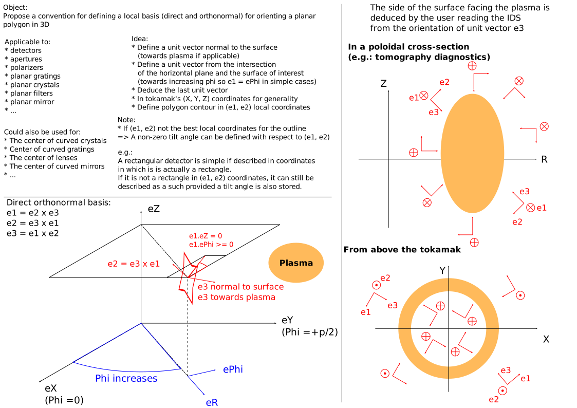
Type of geometry used to describe the surface of the detector or aperture (1:’outline’, 2:’circular’, 3:’rectangle’). In case of ‘outline’, the surface is described by an outline of point in a local coordinate system defined by a centre and three unit vectors X1, X2, X3. Note that there is some flexibility here and the data provider should choose the most convenient coordinate system for the object, respecting the definitions of (X1,X2,X3) indicated below. In case of ‘circular’, the surface is a circle defined by its centre, radius, and normal vector oriented towards the plasma X3. In case of ‘rectangle’, the surface is a rectangle defined by its centre, widths in the X1 and X2 directions, and normal vector oriented towards the plasma X3.
optical_element(i1)/geometry/centrestructure¶If geometry_type=2, coordinates of the centre of the circle. […]
If geometry_type=2, coordinates of the centre of the circle. If geometry_type=1 or 3, coordinates of the origin of the local coordinate system (X1,X2,X3) describing the plane detector/aperture. This origin is located within the detector/aperture area.
optical_element(i1)/geometry/radius ⇹mFLT_0D¶Radius of the circle, used only if geometry_type = 2
Radius of the circle, used only if geometry_type = 2
optical_element(i1)/geometry/x1_unit_vectorstructure¶Components of the X1 direction unit vector in the (X,Y,Z) coordinate […]
Components of the X1 direction unit vector in the (X,Y,Z) coordinate system, where X is the major radius axis for phi = 0, Y is the major radius axis for phi = pi/2, and Z is the height axis. The X1 vector is more horizontal than X2 (has a smaller abs(Z) component) and oriented in the positive phi direction (counter-clockwise when viewing from above).
Click here for further documentation.
optical_element(i1)/geometry/x1_unit_vector/x ⇹mFLT_0D¶Component along X axis
Component along X axis
optical_element(i1)/geometry/x2_unit_vectorstructure¶Components of the X2 direction unit vector in the (X,Y,Z) coordinate […]
Components of the X2 direction unit vector in the (X,Y,Z) coordinate system, where X is the major radius axis for phi = 0, Y is the major radius axis for phi = pi/2, and Z is the height axis. The X2 axis is orthonormal so that uX2 = uX3 x uX1.
Click here for further documentation.
optical_element(i1)/geometry/x2_unit_vector/x ⇹mFLT_0D¶Component along X axis
Component along X axis
optical_element(i1)/geometry/x3_unit_vectorstructure¶Components of the X3 direction unit vector in the (X,Y,Z) coordinate […]
Components of the X3 direction unit vector in the (X,Y,Z) coordinate system, where X is the major radius axis for phi = 0, Y is the major radius axis for phi = pi/2, and Z is the height axis. The X3 axis is normal to the detector/aperture plane and oriented towards the plasma.
Click here for further documentation.
optical_element(i1)/geometry/x3_unit_vector/x ⇹mFLT_0D¶Component along X axis
Component along X axis
optical_element(i1)/geometry/x1_width ⇹mFLT_0D¶Full width of the aperture in the X1 direction, used only if […]
Full width of the aperture in the X1 direction, used only if geometry_type = 3
optical_element(i1)/geometry/x2_width ⇹mFLT_0D¶Full width of the aperture in the X2 direction, used only if […]
Full width of the aperture in the X2 direction, used only if geometry_type = 3
optical_element(i1)/geometry/outlinestructure¶Irregular outline of the detector/aperture in the (X1, X2) coordinate […]
Irregular outline of the detector/aperture in the (X1, X2) coordinate system. Do NOT repeat the first point.
optical_element(i1)/geometry/outline/x1(:) ⇹mFLT_1D¶Positions along x1 axis
Positions along x1 axis
1 |
|
fibre_bundlestructure¶Description of the fibre bundle
Description of the fibre bundle
New in version >3.38.1.
fibre_bundle/geometrystructure¶Geometry of the fibre bundle entrance
Geometry of the fibre bundle entrance
fibre_bundle/geometry/geometry_typeINT_0D¶Type of geometry used to describe the surface of the detector […]
Type of geometry used to describe the surface of the detector or aperture (1:’outline’, 2:’circular’, 3:’rectangle’). In case of ‘outline’, the surface is described by an outline of point in a local coordinate system defined by a centre and three unit vectors X1, X2, X3. Note that there is some flexibility here and the data provider should choose the most convenient coordinate system for the object, respecting the definitions of (X1,X2,X3) indicated below. In case of ‘circular’, the surface is a circle defined by its centre, radius, and normal vector oriented towards the plasma X3. In case of ‘rectangle’, the surface is a rectangle defined by its centre, widths in the X1 and X2 directions, and normal vector oriented towards the plasma X3.
fibre_bundle/geometry/centrestructure¶If geometry_type=2, coordinates of the centre of the circle. […]
If geometry_type=2, coordinates of the centre of the circle. If geometry_type=1 or 3, coordinates of the origin of the local coordinate system (X1,X2,X3) describing the plane detector/aperture. This origin is located within the detector/aperture area.
fibre_bundle/geometry/radius ⇹mFLT_0D¶Radius of the circle, used only if geometry_type = 2
Radius of the circle, used only if geometry_type = 2
fibre_bundle/geometry/x1_unit_vectorstructure¶Components of the X1 direction unit vector in the (X,Y,Z) coordinate […]
Components of the X1 direction unit vector in the (X,Y,Z) coordinate system, where X is the major radius axis for phi = 0, Y is the major radius axis for phi = pi/2, and Z is the height axis. The X1 vector is more horizontal than X2 (has a smaller abs(Z) component) and oriented in the positive phi direction (counter-clockwise when viewing from above).
fibre_bundle/geometry/x2_unit_vectorstructure¶Components of the X2 direction unit vector in the (X,Y,Z) coordinate […]
Components of the X2 direction unit vector in the (X,Y,Z) coordinate system, where X is the major radius axis for phi = 0, Y is the major radius axis for phi = pi/2, and Z is the height axis. The X2 axis is orthonormal so that uX2 = uX3 x uX1.
fibre_bundle/geometry/x3_unit_vectorstructure¶Components of the X3 direction unit vector in the (X,Y,Z) coordinate […]
Components of the X3 direction unit vector in the (X,Y,Z) coordinate system, where X is the major radius axis for phi = 0, Y is the major radius axis for phi = pi/2, and Z is the height axis. The X3 axis is normal to the detector/aperture plane and oriented towards the plasma.
fibre_bundle/geometry/x1_width ⇹mFLT_0D¶Full width of the aperture in the X1 direction, used only if […]
Full width of the aperture in the X1 direction, used only if geometry_type = 3
fibre_bundle/geometry/x2_width ⇹mFLT_0D¶Full width of the aperture in the X2 direction, used only if […]
Full width of the aperture in the X2 direction, used only if geometry_type = 3
fibre_bundle/geometry/outlinestructure¶Irregular outline of the detector/aperture in the (X1, X2) coordinate […]
Irregular outline of the detector/aperture in the (X1, X2) coordinate system. Do NOT repeat the first point.
fibre_bundle/geometry/outline/x1(:) ⇹mFLT_1D¶Positions along x1 axis
Positions along x1 axis
1 |
|
fibre_bundle/fibre_positionsstructure¶Individual fibres centres positions in the (X1, X2) coordinate […]
Individual fibres centres positions in the (X1, X2) coordinate system