pulse_schedule
Description of Pulse Schedule, described by subsystems waveform references and an enveloppe around them. The controllers, pulse schedule and SDN are defined in separate IDSs. All names and identifiers of subsystems appearing in the pulse_schedule must be identical to those used in the IDSs describing the related subsystems.
Maximum occurrences (MDS+ backend only): 1
New in version 3.6.0: lifecycle status alpha
Changed in version 3.42.0.
ids_propertiesstructure
See common IDS structure reference: ids_properties.
icstructure¶Ion cyclotron heating and current drive system
Ion cyclotron heating and current drive system
ic/antenna(i1)AoS¶Set of ICRH antennas
Set of ICRH antennas
Maximum occurrences (MDS+ backend only): 3
1 |
|
ic/antenna(i1)/power_typestructure¶Type of power used in the sibling power node (defining which […]
Type of power used in the sibling power node (defining which power is referred to in this pulse_schedule). Index = 1: power_launched, 2: power_forward (see definitions in the ic_antennas IDS)
ic/antenna(i1)/powerWstructure¶Power
Power
ic/antenna(i1)/power/reference_nameSTR_0D¶Reference name (e.g. […]
Reference name (e.g. in the native pulse schedule system of the device)
ic/antenna(i1)/power/reference(:) ⇹mixedFLT_1D¶Reference waveform. […]
Reference waveform. Caution : error bars of the reference/data node are not used in the usual sense, instead they are used to describe the control envelope, with a meaning depending on the chosen envelope_type option.
1 |
Changed in version 3.40.0: Renamed from reference/data
ic/antenna(i1)/power/reference_typeINT_0D¶Reference type: 0:relative (don’t use for the moment, to be […]
Reference type: 0:relative (don’t use for the moment, to be defined later when segments are introduced in the IDS structure); 1: absolute: the reference time trace is provided in the reference/data node
ic/antenna(i1)/power/envelope_typeINT_0D¶Envelope type: 0:relative: means that the envelope upper and […]
Envelope type: 0:relative: means that the envelope upper and lower bound values are defined respectively as reference.data * reference.data_error_upper and reference.data * reference.data_error_lower. 1: absolute: the envelope upper and lower bound values are given respectively by reference/data_error_upper and reference/data_error_lower. Lower and upper are taken in the strict mathematical sense, without considering absolute values of the data
ic/antenna(i1)/phaseradstructure¶Phase
Phase
ic/antenna(i1)/phase/reference_nameSTR_0D¶Reference name (e.g. […]
Reference name (e.g. in the native pulse schedule system of the device)
ic/antenna(i1)/phase/reference(:) ⇹mixedFLT_1D¶Reference waveform. […]
Reference waveform. Caution : error bars of the reference/data node are not used in the usual sense, instead they are used to describe the control envelope, with a meaning depending on the chosen envelope_type option.
1 |
Changed in version 3.40.0: Renamed from reference/data
ic/antenna(i1)/phase/reference_typeINT_0D¶Reference type: 0:relative (don’t use for the moment, to be […]
Reference type: 0:relative (don’t use for the moment, to be defined later when segments are introduced in the IDS structure); 1: absolute: the reference time trace is provided in the reference/data node
ic/antenna(i1)/phase/envelope_typeINT_0D¶Envelope type: 0:relative: means that the envelope upper and […]
Envelope type: 0:relative: means that the envelope upper and lower bound values are defined respectively as reference.data * reference.data_error_upper and reference.data * reference.data_error_lower. 1: absolute: the envelope upper and lower bound values are given respectively by reference/data_error_upper and reference/data_error_lower. Lower and upper are taken in the strict mathematical sense, without considering absolute values of the data
ic/antenna(i1)/frequencyHzstructure¶Frequency
Frequency
ic/antenna(i1)/frequency/reference_nameSTR_0D¶Reference name (e.g. […]
Reference name (e.g. in the native pulse schedule system of the device)
ic/antenna(i1)/frequency/reference(:) ⇹mixedFLT_1D¶Reference waveform. […]
Reference waveform. Caution : error bars of the reference/data node are not used in the usual sense, instead they are used to describe the control envelope, with a meaning depending on the chosen envelope_type option.
1 |
Changed in version 3.40.0: Renamed from reference/data
ic/antenna(i1)/frequency/reference_typeINT_0D¶Reference type: 0:relative (don’t use for the moment, to be […]
Reference type: 0:relative (don’t use for the moment, to be defined later when segments are introduced in the IDS structure); 1: absolute: the reference time trace is provided in the reference/data node
ic/antenna(i1)/frequency/envelope_typeINT_0D¶Envelope type: 0:relative: means that the envelope upper and […]
Envelope type: 0:relative: means that the envelope upper and lower bound values are defined respectively as reference.data * reference.data_error_upper and reference.data * reference.data_error_lower. 1: absolute: the envelope upper and lower bound values are given respectively by reference/data_error_upper and reference/data_error_lower. Lower and upper are taken in the strict mathematical sense, without considering absolute values of the data
ic/powerWstructure¶Total IC power (sum over the antennas)
Total IC power (sum over the antennas)
New in version >3.39.0.
ic/power/reference_nameSTR_0D¶Reference name (e.g. […]
Reference name (e.g. in the native pulse schedule system of the device)
ic/power/reference(:) ⇹mixedFLT_1D¶Reference waveform. […]
Reference waveform. Caution : error bars of the reference/data node are not used in the usual sense, instead they are used to describe the control envelope, with a meaning depending on the chosen envelope_type option.
1 |
Changed in version 3.40.0: Renamed from reference/data
ic/power/reference_typeINT_0D¶Reference type: 0:relative (don’t use for the moment, to be […]
Reference type: 0:relative (don’t use for the moment, to be defined later when segments are introduced in the IDS structure); 1: absolute: the reference time trace is provided in the reference/data node
ic/power/envelope_typeINT_0D¶Envelope type: 0:relative: means that the envelope upper and […]
Envelope type: 0:relative: means that the envelope upper and lower bound values are defined respectively as reference.data * reference.data_error_upper and reference.data * reference.data_error_lower. 1: absolute: the envelope upper and lower bound values are given respectively by reference/data_error_upper and reference/data_error_lower. Lower and upper are taken in the strict mathematical sense, without considering absolute values of the data
ic/mode(:)INT_1D¶Control mode (operation mode and/or settings used by the controller)
Control mode (operation mode and/or settings used by the controller)
1 |
Changed in version 3.40.0: Renamed from mode/data
ecstructure¶Electron cyclotron heating and current drive system
Electron cyclotron heating and current drive system
ec/beam(i1)AoS¶Set of Electron Cyclotron beams
Set of Electron Cyclotron beams
Maximum occurrences (MDS+ backend only): 100
1 |
|
Changed in version 3.26.0,3.40.0: Renamed from antenna,launcher
ec/beam(i1)/power_launchedWstructure¶Beam power launched into the vacuum vessel
Beam power launched into the vacuum vessel
Changed in version 3.40.0: Renamed from power
ec/beam(i1)/power_launched/reference_nameSTR_0D¶Reference name (e.g. […]
Reference name (e.g. in the native pulse schedule system of the device)
ec/beam(i1)/power_launched/reference(:) ⇹mixedFLT_1D¶Reference waveform. […]
Reference waveform. Caution : error bars of the reference/data node are not used in the usual sense, instead they are used to describe the control envelope, with a meaning depending on the chosen envelope_type option.
1 |
Changed in version 3.40.0: Renamed from reference/data
ec/beam(i1)/power_launched/reference_typeINT_0D¶Reference type: 0:relative (don’t use for the moment, to be […]
Reference type: 0:relative (don’t use for the moment, to be defined later when segments are introduced in the IDS structure); 1: absolute: the reference time trace is provided in the reference/data node
ec/beam(i1)/power_launched/envelope_typeINT_0D¶Envelope type: 0:relative: means that the envelope upper and […]
Envelope type: 0:relative: means that the envelope upper and lower bound values are defined respectively as reference.data * reference.data_error_upper and reference.data * reference.data_error_lower. 1: absolute: the envelope upper and lower bound values are given respectively by reference/data_error_upper and reference/data_error_lower. Lower and upper are taken in the strict mathematical sense, without considering absolute values of the data
ec/beam(i1)/frequencyHzstructure¶Frequency
Frequency
ec/beam(i1)/frequency/reference_nameSTR_0D¶Reference name (e.g. […]
Reference name (e.g. in the native pulse schedule system of the device)
ec/beam(i1)/frequency/reference(:) ⇹mixedFLT_1D¶Reference waveform. […]
Reference waveform. Caution : error bars of the reference/data node are not used in the usual sense, instead they are used to describe the control envelope, with a meaning depending on the chosen envelope_type option.
1 |
Changed in version 3.40.0: Renamed from reference/data
ec/beam(i1)/frequency/reference_typeINT_0D¶Reference type: 0:relative (don’t use for the moment, to be […]
Reference type: 0:relative (don’t use for the moment, to be defined later when segments are introduced in the IDS structure); 1: absolute: the reference time trace is provided in the reference/data node
ec/beam(i1)/frequency/envelope_typeINT_0D¶Envelope type: 0:relative: means that the envelope upper and […]
Envelope type: 0:relative: means that the envelope upper and lower bound values are defined respectively as reference.data * reference.data_error_upper and reference.data * reference.data_error_lower. 1: absolute: the envelope upper and lower bound values are given respectively by reference/data_error_upper and reference/data_error_lower. Lower and upper are taken in the strict mathematical sense, without considering absolute values of the data
ec/beam(i1)/deposition_rho_tor_norm-structure¶Normalised toroidal flux coordinate at which the main deposition […]
Normalised toroidal flux coordinate at which the main deposition should occur
ec/beam(i1)/deposition_rho_tor_norm/reference_nameSTR_0D¶Reference name (e.g. […]
Reference name (e.g. in the native pulse schedule system of the device)
ec/beam(i1)/deposition_rho_tor_norm/reference(:) ⇹mixedFLT_1D¶Reference waveform. […]
Reference waveform. Caution : error bars of the reference/data node are not used in the usual sense, instead they are used to describe the control envelope, with a meaning depending on the chosen envelope_type option.
1 |
Changed in version 3.40.0: Renamed from reference/data
ec/beam(i1)/deposition_rho_tor_norm/reference_typeINT_0D¶Reference type: 0:relative (don’t use for the moment, to be […]
Reference type: 0:relative (don’t use for the moment, to be defined later when segments are introduced in the IDS structure); 1: absolute: the reference time trace is provided in the reference/data node
ec/beam(i1)/deposition_rho_tor_norm/envelope_typeINT_0D¶Envelope type: 0:relative: means that the envelope upper and […]
Envelope type: 0:relative: means that the envelope upper and lower bound values are defined respectively as reference.data * reference.data_error_upper and reference.data * reference.data_error_lower. 1: absolute: the envelope upper and lower bound values are given respectively by reference/data_error_upper and reference/data_error_lower. Lower and upper are taken in the strict mathematical sense, without considering absolute values of the data
ec/beam(i1)/steering_angle_polradstructure¶Steering angle of the EC beam in the R,Z plane (from the -R axis […]
Steering angle of the EC beam in the R,Z plane (from the -R axis towards the -Z axis), angle_pol=atan2(-k_Z,-k_R), where k_Z and k_R are the Z and R components of the mean wave vector in the EC beam
Changed in version 3.26.0: Renamed from launching_angle_pol
ec/beam(i1)/steering_angle_pol/reference_nameSTR_0D¶Reference name (e.g. […]
Reference name (e.g. in the native pulse schedule system of the device)
ec/beam(i1)/steering_angle_pol/reference(:) ⇹mixedFLT_1D¶Reference waveform. […]
Reference waveform. Caution : error bars of the reference/data node are not used in the usual sense, instead they are used to describe the control envelope, with a meaning depending on the chosen envelope_type option.
1 |
Changed in version 3.40.0: Renamed from reference/data
ec/beam(i1)/steering_angle_pol/reference_typeINT_0D¶Reference type: 0:relative (don’t use for the moment, to be […]
Reference type: 0:relative (don’t use for the moment, to be defined later when segments are introduced in the IDS structure); 1: absolute: the reference time trace is provided in the reference/data node
ec/beam(i1)/steering_angle_pol/envelope_typeINT_0D¶Envelope type: 0:relative: means that the envelope upper and […]
Envelope type: 0:relative: means that the envelope upper and lower bound values are defined respectively as reference.data * reference.data_error_upper and reference.data * reference.data_error_lower. 1: absolute: the envelope upper and lower bound values are given respectively by reference/data_error_upper and reference/data_error_lower. Lower and upper are taken in the strict mathematical sense, without considering absolute values of the data
ec/beam(i1)/steering_angle_torradstructure¶Steering angle of the EC beam away from the poloidal plane that […]
Steering angle of the EC beam away from the poloidal plane that is increasing towards the positive phi axis, angle_tor=arcsin(k_phi/k), where k_phi is the component of the wave vector in the phi direction and k is the length of the wave vector. Here the term wave vector refers to the mean wave vector in the EC beam
Changed in version 3.26.0: Renamed from launching_angle_tor
ec/beam(i1)/steering_angle_tor/reference_nameSTR_0D¶Reference name (e.g. […]
Reference name (e.g. in the native pulse schedule system of the device)
ec/beam(i1)/steering_angle_tor/reference(:) ⇹mixedFLT_1D¶Reference waveform. […]
Reference waveform. Caution : error bars of the reference/data node are not used in the usual sense, instead they are used to describe the control envelope, with a meaning depending on the chosen envelope_type option.
1 |
Changed in version 3.40.0: Renamed from reference/data
ec/beam(i1)/steering_angle_tor/reference_typeINT_0D¶Reference type: 0:relative (don’t use for the moment, to be […]
Reference type: 0:relative (don’t use for the moment, to be defined later when segments are introduced in the IDS structure); 1: absolute: the reference time trace is provided in the reference/data node
ec/beam(i1)/steering_angle_tor/envelope_typeINT_0D¶Envelope type: 0:relative: means that the envelope upper and […]
Envelope type: 0:relative: means that the envelope upper and lower bound values are defined respectively as reference.data * reference.data_error_upper and reference.data * reference.data_error_lower. 1: absolute: the envelope upper and lower bound values are given respectively by reference/data_error_upper and reference/data_error_lower. Lower and upper are taken in the strict mathematical sense, without considering absolute values of the data
ec/power_launchedWstructure¶Total EC power launched in the plasma (sum over the beams)
Total EC power launched in the plasma (sum over the beams)
Changed in version 3.40.0: Renamed from power
New in version >3.34.0.
ec/power_launched/reference_nameSTR_0D¶Reference name (e.g. […]
Reference name (e.g. in the native pulse schedule system of the device)
ec/power_launched/reference(:) ⇹mixedFLT_1D¶Reference waveform. […]
Reference waveform. Caution : error bars of the reference/data node are not used in the usual sense, instead they are used to describe the control envelope, with a meaning depending on the chosen envelope_type option.
1 |
Changed in version 3.40.0: Renamed from reference/data
ec/power_launched/reference_typeINT_0D¶Reference type: 0:relative (don’t use for the moment, to be […]
Reference type: 0:relative (don’t use for the moment, to be defined later when segments are introduced in the IDS structure); 1: absolute: the reference time trace is provided in the reference/data node
ec/power_launched/envelope_typeINT_0D¶Envelope type: 0:relative: means that the envelope upper and […]
Envelope type: 0:relative: means that the envelope upper and lower bound values are defined respectively as reference.data * reference.data_error_upper and reference.data * reference.data_error_lower. 1: absolute: the envelope upper and lower bound values are given respectively by reference/data_error_upper and reference/data_error_lower. Lower and upper are taken in the strict mathematical sense, without considering absolute values of the data
ec/mode(:)INT_1D¶Control mode (operation mode and/or settings used by the controller)
Control mode (operation mode and/or settings used by the controller)
1 |
Changed in version 3.40.0: Renamed from mode/data
lhstructure¶Lower Hybrid heating and current drive system
Lower Hybrid heating and current drive system
lh/antenna(i1)AoS¶Set of LH antennas
Set of LH antennas
Maximum occurrences (MDS+ backend only): 3
1 |
|
lh/antenna(i1)/power_typestructure¶Type of power used in the sibling power node (defining which […]
Type of power used in the sibling power node (defining which power is referred to in this pulse_schedule). Index = 1: power_launched, 2: power_forward (see definitions in the lh_antennas IDS)
lh/antenna(i1)/powerWstructure¶Power
Power
lh/antenna(i1)/power/reference_nameSTR_0D¶Reference name (e.g. […]
Reference name (e.g. in the native pulse schedule system of the device)
lh/antenna(i1)/power/reference(:) ⇹mixedFLT_1D¶Reference waveform. […]
Reference waveform. Caution : error bars of the reference/data node are not used in the usual sense, instead they are used to describe the control envelope, with a meaning depending on the chosen envelope_type option.
1 |
Changed in version 3.40.0: Renamed from reference/data
lh/antenna(i1)/power/reference_typeINT_0D¶Reference type: 0:relative (don’t use for the moment, to be […]
Reference type: 0:relative (don’t use for the moment, to be defined later when segments are introduced in the IDS structure); 1: absolute: the reference time trace is provided in the reference/data node
lh/antenna(i1)/power/envelope_typeINT_0D¶Envelope type: 0:relative: means that the envelope upper and […]
Envelope type: 0:relative: means that the envelope upper and lower bound values are defined respectively as reference.data * reference.data_error_upper and reference.data * reference.data_error_lower. 1: absolute: the envelope upper and lower bound values are given respectively by reference/data_error_upper and reference/data_error_lower. Lower and upper are taken in the strict mathematical sense, without considering absolute values of the data
lh/antenna(i1)/phaseradstructure¶Phasing between neighbour waveguides (in the toroidal direction)
Phasing between neighbour waveguides (in the toroidal direction)
lh/antenna(i1)/phase/reference_nameSTR_0D¶Reference name (e.g. […]
Reference name (e.g. in the native pulse schedule system of the device)
lh/antenna(i1)/phase/reference(:) ⇹mixedFLT_1D¶Reference waveform. […]
Reference waveform. Caution : error bars of the reference/data node are not used in the usual sense, instead they are used to describe the control envelope, with a meaning depending on the chosen envelope_type option.
1 |
Changed in version 3.40.0: Renamed from reference/data
lh/antenna(i1)/phase/reference_typeINT_0D¶Reference type: 0:relative (don’t use for the moment, to be […]
Reference type: 0:relative (don’t use for the moment, to be defined later when segments are introduced in the IDS structure); 1: absolute: the reference time trace is provided in the reference/data node
lh/antenna(i1)/phase/envelope_typeINT_0D¶Envelope type: 0:relative: means that the envelope upper and […]
Envelope type: 0:relative: means that the envelope upper and lower bound values are defined respectively as reference.data * reference.data_error_upper and reference.data * reference.data_error_lower. 1: absolute: the envelope upper and lower bound values are given respectively by reference/data_error_upper and reference/data_error_lower. Lower and upper are taken in the strict mathematical sense, without considering absolute values of the data
lh/antenna(i1)/n_parallel-structure¶Main parallel refractive index of the injected wave power spectrum
Main parallel refractive index of the injected wave power spectrum
lh/antenna(i1)/n_parallel/reference_nameSTR_0D¶Reference name (e.g. […]
Reference name (e.g. in the native pulse schedule system of the device)
lh/antenna(i1)/n_parallel/reference(:) ⇹mixedFLT_1D¶Reference waveform. […]
Reference waveform. Caution : error bars of the reference/data node are not used in the usual sense, instead they are used to describe the control envelope, with a meaning depending on the chosen envelope_type option.
1 |
Changed in version 3.40.0: Renamed from reference/data
lh/antenna(i1)/n_parallel/reference_typeINT_0D¶Reference type: 0:relative (don’t use for the moment, to be […]
Reference type: 0:relative (don’t use for the moment, to be defined later when segments are introduced in the IDS structure); 1: absolute: the reference time trace is provided in the reference/data node
lh/antenna(i1)/n_parallel/envelope_typeINT_0D¶Envelope type: 0:relative: means that the envelope upper and […]
Envelope type: 0:relative: means that the envelope upper and lower bound values are defined respectively as reference.data * reference.data_error_upper and reference.data * reference.data_error_lower. 1: absolute: the envelope upper and lower bound values are given respectively by reference/data_error_upper and reference/data_error_lower. Lower and upper are taken in the strict mathematical sense, without considering absolute values of the data
lh/antenna(i1)/frequencyHzstructure¶Frequency
Frequency
lh/antenna(i1)/frequency/reference_nameSTR_0D¶Reference name (e.g. […]
Reference name (e.g. in the native pulse schedule system of the device)
lh/antenna(i1)/frequency/reference(:) ⇹mixedFLT_1D¶Reference waveform. […]
Reference waveform. Caution : error bars of the reference/data node are not used in the usual sense, instead they are used to describe the control envelope, with a meaning depending on the chosen envelope_type option.
1 |
Changed in version 3.40.0: Renamed from reference/data
lh/antenna(i1)/frequency/reference_typeINT_0D¶Reference type: 0:relative (don’t use for the moment, to be […]
Reference type: 0:relative (don’t use for the moment, to be defined later when segments are introduced in the IDS structure); 1: absolute: the reference time trace is provided in the reference/data node
lh/antenna(i1)/frequency/envelope_typeINT_0D¶Envelope type: 0:relative: means that the envelope upper and […]
Envelope type: 0:relative: means that the envelope upper and lower bound values are defined respectively as reference.data * reference.data_error_upper and reference.data * reference.data_error_lower. 1: absolute: the envelope upper and lower bound values are given respectively by reference/data_error_upper and reference/data_error_lower. Lower and upper are taken in the strict mathematical sense, without considering absolute values of the data
lh/powerWstructure¶Total LH power (sum over the antennas)
Total LH power (sum over the antennas)
New in version >3.39.0.
lh/power/reference_nameSTR_0D¶Reference name (e.g. […]
Reference name (e.g. in the native pulse schedule system of the device)
lh/power/reference(:) ⇹mixedFLT_1D¶Reference waveform. […]
Reference waveform. Caution : error bars of the reference/data node are not used in the usual sense, instead they are used to describe the control envelope, with a meaning depending on the chosen envelope_type option.
1 |
Changed in version 3.40.0: Renamed from reference/data
lh/power/reference_typeINT_0D¶Reference type: 0:relative (don’t use for the moment, to be […]
Reference type: 0:relative (don’t use for the moment, to be defined later when segments are introduced in the IDS structure); 1: absolute: the reference time trace is provided in the reference/data node
lh/power/envelope_typeINT_0D¶Envelope type: 0:relative: means that the envelope upper and […]
Envelope type: 0:relative: means that the envelope upper and lower bound values are defined respectively as reference.data * reference.data_error_upper and reference.data * reference.data_error_lower. 1: absolute: the envelope upper and lower bound values are given respectively by reference/data_error_upper and reference/data_error_lower. Lower and upper are taken in the strict mathematical sense, without considering absolute values of the data
lh/mode(:)INT_1D¶Control mode (operation mode and/or settings used by the controller)
Control mode (operation mode and/or settings used by the controller)
1 |
Changed in version 3.40.0: Renamed from mode/data
nbistructure¶Neutral beam heating and current drive system
Neutral beam heating and current drive system
nbi/unit(i1)AoS¶Set of NBI units
Set of NBI units
Maximum occurrences (MDS+ backend only): 36
1 |
|
nbi/unit(i1)/species(i2)AoS¶Species injected by the NBI unit (may be more than one in case […]
Species injected by the NBI unit (may be more than one in case the unit injects a gas mixture)
Maximum occurrences (MDS+ backend only): 3
1 |
|
nbi/unit(i1)/species(i2)/element(i3)AoS¶List of elements forming the atom or molecule
List of elements forming the atom or molecule
Maximum occurrences (MDS+ backend only): 5
1 |
|
nbi/unit(i1)/species(i2)/element(i3)/z_n ⇹Elementary Charge UnitFLT_0D¶Nuclear charge
Nuclear charge
nbi/unit(i1)/species(i2)/labelSTR_0D¶String identifying neutral (e.g. […]
String identifying neutral (e.g. H, D, T, He, C, …)
Deprecated since version 3.42.0.
nbi/unit(i1)/powerWstructure¶Power launched from this unit into the vacuum vessel
Power launched from this unit into the vacuum vessel
nbi/unit(i1)/power/reference_nameSTR_0D¶Reference name (e.g. […]
Reference name (e.g. in the native pulse schedule system of the device)
nbi/unit(i1)/power/reference(:) ⇹mixedFLT_1D¶Reference waveform. […]
Reference waveform. Caution : error bars of the reference/data node are not used in the usual sense, instead they are used to describe the control envelope, with a meaning depending on the chosen envelope_type option.
1 |
Changed in version 3.40.0: Renamed from reference/data
nbi/unit(i1)/power/reference_typeINT_0D¶Reference type: 0:relative (don’t use for the moment, to be […]
Reference type: 0:relative (don’t use for the moment, to be defined later when segments are introduced in the IDS structure); 1: absolute: the reference time trace is provided in the reference/data node
nbi/unit(i1)/power/envelope_typeINT_0D¶Envelope type: 0:relative: means that the envelope upper and […]
Envelope type: 0:relative: means that the envelope upper and lower bound values are defined respectively as reference.data * reference.data_error_upper and reference.data * reference.data_error_lower. 1: absolute: the envelope upper and lower bound values are given respectively by reference/data_error_upper and reference/data_error_lower. Lower and upper are taken in the strict mathematical sense, without considering absolute values of the data
nbi/unit(i1)/energyeVstructure¶Full energy of the injected species (acceleration of a single […]
Full energy of the injected species (acceleration of a single atom)
nbi/unit(i1)/energy/reference_nameSTR_0D¶Reference name (e.g. […]
Reference name (e.g. in the native pulse schedule system of the device)
nbi/unit(i1)/energy/reference(:) ⇹mixedFLT_1D¶Reference waveform. […]
Reference waveform. Caution : error bars of the reference/data node are not used in the usual sense, instead they are used to describe the control envelope, with a meaning depending on the chosen envelope_type option.
1 |
Changed in version 3.40.0: Renamed from reference/data
nbi/unit(i1)/energy/reference_typeINT_0D¶Reference type: 0:relative (don’t use for the moment, to be […]
Reference type: 0:relative (don’t use for the moment, to be defined later when segments are introduced in the IDS structure); 1: absolute: the reference time trace is provided in the reference/data node
nbi/unit(i1)/energy/envelope_typeINT_0D¶Envelope type: 0:relative: means that the envelope upper and […]
Envelope type: 0:relative: means that the envelope upper and lower bound values are defined respectively as reference.data * reference.data_error_upper and reference.data * reference.data_error_lower. 1: absolute: the envelope upper and lower bound values are given respectively by reference/data_error_upper and reference/data_error_lower. Lower and upper are taken in the strict mathematical sense, without considering absolute values of the data
nbi/powerWstructure¶Total NBI power (sum over the units)
Total NBI power (sum over the units)
New in version >3.34.0.
nbi/power/reference_nameSTR_0D¶Reference name (e.g. […]
Reference name (e.g. in the native pulse schedule system of the device)
nbi/power/reference(:) ⇹mixedFLT_1D¶Reference waveform. […]
Reference waveform. Caution : error bars of the reference/data node are not used in the usual sense, instead they are used to describe the control envelope, with a meaning depending on the chosen envelope_type option.
1 |
Changed in version 3.40.0: Renamed from reference/data
nbi/power/reference_typeINT_0D¶Reference type: 0:relative (don’t use for the moment, to be […]
Reference type: 0:relative (don’t use for the moment, to be defined later when segments are introduced in the IDS structure); 1: absolute: the reference time trace is provided in the reference/data node
nbi/power/envelope_typeINT_0D¶Envelope type: 0:relative: means that the envelope upper and […]
Envelope type: 0:relative: means that the envelope upper and lower bound values are defined respectively as reference.data * reference.data_error_upper and reference.data * reference.data_error_lower. 1: absolute: the envelope upper and lower bound values are given respectively by reference/data_error_upper and reference/data_error_lower. Lower and upper are taken in the strict mathematical sense, without considering absolute values of the data
nbi/mode(:)INT_1D¶Control mode (operation mode and/or settings used by the controller)
Control mode (operation mode and/or settings used by the controller)
1 |
Changed in version 3.40.0: Renamed from mode/data
density_controlstructure¶Gas injection system and density control references
Gas injection system and density control references
density_control/valve(i1)AoS¶Set of injection valves. […]
Set of injection valves. Time-dependent
Maximum occurrences (MDS+ backend only): 20
1 |
|
density_control/valve(i1)/flow_ratePa.m^3.s^-1structure¶Flow rate of the valve
Flow rate of the valve
density_control/valve(i1)/flow_rate/reference_nameSTR_0D¶Reference name (e.g. […]
Reference name (e.g. in the native pulse schedule system of the device)
density_control/valve(i1)/flow_rate/reference(:) ⇹mixedFLT_1D¶Reference waveform. […]
Reference waveform. Caution : error bars of the reference/data node are not used in the usual sense, instead they are used to describe the control envelope, with a meaning depending on the chosen envelope_type option.
1 |
Changed in version 3.40.0: Renamed from reference/data
density_control/valve(i1)/flow_rate/reference_typeINT_0D¶Reference type: 0:relative (don’t use for the moment, to be […]
Reference type: 0:relative (don’t use for the moment, to be defined later when segments are introduced in the IDS structure); 1: absolute: the reference time trace is provided in the reference/data node
density_control/valve(i1)/flow_rate/envelope_typeINT_0D¶Envelope type: 0:relative: means that the envelope upper and […]
Envelope type: 0:relative: means that the envelope upper and lower bound values are defined respectively as reference.data * reference.data_error_upper and reference.data * reference.data_error_lower. 1: absolute: the envelope upper and lower bound values are given respectively by reference/data_error_upper and reference/data_error_lower. Lower and upper are taken in the strict mathematical sense, without considering absolute values of the data
density_control/valve(i1)/species(i2)AoS¶Species injected by the valve (may be more than one in case the […]
Species injected by the valve (may be more than one in case the valve injects a gas mixture)
Maximum occurrences (MDS+ backend only): 3
1 |
|
density_control/valve(i1)/species(i2)/element(i3)AoS¶List of elements forming the atom or molecule
List of elements forming the atom or molecule
Maximum occurrences (MDS+ backend only): 5
1 |
|
density_control/valve(i1)/species(i2)/element(i3)/a ⇹Atomic Mass UnitFLT_0D¶Mass of atom
Mass of atom
density_control/valve(i1)/species(i2)/element(i3)/z_n ⇹Elementary Charge UnitFLT_0D¶Nuclear charge
Nuclear charge
density_control/valve(i1)/species(i2)/labelSTR_0D¶String identifying neutral (e.g. […]
String identifying neutral (e.g. H, D, T, He, C, …)
Deprecated since version 3.42.0.
density_control/n_e_linem^-2structure¶Line integrated electron density over a line of sight in the […]
Line integrated electron density over a line of sight in the whole vacuum chamber
density_control/n_e_line/reference_nameSTR_0D¶Reference name (e.g. […]
Reference name (e.g. in the native pulse schedule system of the device)
density_control/n_e_line/reference(:) ⇹mixedFLT_1D¶Reference waveform. […]
Reference waveform. Caution : error bars of the reference/data node are not used in the usual sense, instead they are used to describe the control envelope, with a meaning depending on the chosen envelope_type option.
1 |
Changed in version 3.40.0: Renamed from reference/data
density_control/n_e_line/reference_typeINT_0D¶Reference type: 0:relative (don’t use for the moment, to be […]
Reference type: 0:relative (don’t use for the moment, to be defined later when segments are introduced in the IDS structure); 1: absolute: the reference time trace is provided in the reference/data node
density_control/n_e_line/envelope_typeINT_0D¶Envelope type: 0:relative: means that the envelope upper and […]
Envelope type: 0:relative: means that the envelope upper and lower bound values are defined respectively as reference.data * reference.data_error_upper and reference.data * reference.data_error_lower. 1: absolute: the envelope upper and lower bound values are given respectively by reference/data_error_upper and reference/data_error_lower. Lower and upper are taken in the strict mathematical sense, without considering absolute values of the data
density_control/n_e_line_lcfsm^-2structure¶Line integrated electron density over a line of sight within […]
Line integrated electron density over a line of sight within the LCFS
New in version >3.38.1.
density_control/n_e_line_lcfs/reference_nameSTR_0D¶Reference name (e.g. […]
Reference name (e.g. in the native pulse schedule system of the device)
density_control/n_e_line_lcfs/reference(:) ⇹mixedFLT_1D¶Reference waveform. […]
Reference waveform. Caution : error bars of the reference/data node are not used in the usual sense, instead they are used to describe the control envelope, with a meaning depending on the chosen envelope_type option.
1 |
Changed in version 3.40.0: Renamed from reference/data
density_control/n_e_line_lcfs/reference_typeINT_0D¶Reference type: 0:relative (don’t use for the moment, to be […]
Reference type: 0:relative (don’t use for the moment, to be defined later when segments are introduced in the IDS structure); 1: absolute: the reference time trace is provided in the reference/data node
density_control/n_e_line_lcfs/envelope_typeINT_0D¶Envelope type: 0:relative: means that the envelope upper and […]
Envelope type: 0:relative: means that the envelope upper and lower bound values are defined respectively as reference.data * reference.data_error_upper and reference.data * reference.data_error_lower. 1: absolute: the envelope upper and lower bound values are given respectively by reference/data_error_upper and reference/data_error_lower. Lower and upper are taken in the strict mathematical sense, without considering absolute values of the data
density_control/n_e_profile_averagem^-3structure¶Integral of a 1D core profile over rho_tor_norm up to the LCFS
Integral of a 1D core profile over rho_tor_norm up to the LCFS
New in version >3.38.1.
density_control/n_e_profile_average/reference_nameSTR_0D¶Reference name (e.g. […]
Reference name (e.g. in the native pulse schedule system of the device)
density_control/n_e_profile_average/reference(:) ⇹mixedFLT_1D¶Reference waveform. […]
Reference waveform. Caution : error bars of the reference/data node are not used in the usual sense, instead they are used to describe the control envelope, with a meaning depending on the chosen envelope_type option.
1 |
Changed in version 3.40.0: Renamed from reference/data
density_control/n_e_profile_average/reference_typeINT_0D¶Reference type: 0:relative (don’t use for the moment, to be […]
Reference type: 0:relative (don’t use for the moment, to be defined later when segments are introduced in the IDS structure); 1: absolute: the reference time trace is provided in the reference/data node
density_control/n_e_profile_average/envelope_typeINT_0D¶Envelope type: 0:relative: means that the envelope upper and […]
Envelope type: 0:relative: means that the envelope upper and lower bound values are defined respectively as reference.data * reference.data_error_upper and reference.data * reference.data_error_lower. 1: absolute: the envelope upper and lower bound values are given respectively by reference/data_error_upper and reference/data_error_lower. Lower and upper are taken in the strict mathematical sense, without considering absolute values of the data
density_control/n_e_line_of_sightstructure¶Description of the line of sight for calculating n_e, defined […]
Description of the line of sight for calculating n_e, defined by two points when the beam is not reflected, a third point is added to define the reflected beam path
New in version >3.34.0.
density_control/n_e_line_of_sight/first_pointstructure¶Position of the first point
Position of the first point
density_control/n_e_line_of_sight/second_pointstructure¶Position of the second point
Position of the second point
density_control/n_e_line_of_sight/third_pointstructure¶Position of the third point
Position of the third point
density_control/n_e_volume_averagem^-3structure¶Volume averaged electron density (average over the plasma volume […]
Volume averaged electron density (average over the plasma volume up to the LCFS)
New in version >3.34.0.
density_control/n_e_volume_average/reference_nameSTR_0D¶Reference name (e.g. […]
Reference name (e.g. in the native pulse schedule system of the device)
density_control/n_e_volume_average/reference(:) ⇹mixedFLT_1D¶Reference waveform. […]
Reference waveform. Caution : error bars of the reference/data node are not used in the usual sense, instead they are used to describe the control envelope, with a meaning depending on the chosen envelope_type option.
1 |
Changed in version 3.40.0: Renamed from reference/data
density_control/n_e_volume_average/reference_typeINT_0D¶Reference type: 0:relative (don’t use for the moment, to be […]
Reference type: 0:relative (don’t use for the moment, to be defined later when segments are introduced in the IDS structure); 1: absolute: the reference time trace is provided in the reference/data node
density_control/n_e_volume_average/envelope_typeINT_0D¶Envelope type: 0:relative: means that the envelope upper and […]
Envelope type: 0:relative: means that the envelope upper and lower bound values are defined respectively as reference.data * reference.data_error_upper and reference.data * reference.data_error_lower. 1: absolute: the envelope upper and lower bound values are given respectively by reference/data_error_upper and reference/data_error_lower. Lower and upper are taken in the strict mathematical sense, without considering absolute values of the data
density_control/zeff-structure¶Line averaged effective charge
Line averaged effective charge
density_control/zeff/reference_nameSTR_0D¶Reference name (e.g. […]
Reference name (e.g. in the native pulse schedule system of the device)
density_control/zeff/reference(:) ⇹mixedFLT_1D¶Reference waveform. […]
Reference waveform. Caution : error bars of the reference/data node are not used in the usual sense, instead they are used to describe the control envelope, with a meaning depending on the chosen envelope_type option.
1 |
Changed in version 3.40.0: Renamed from reference/data
density_control/zeff/reference_typeINT_0D¶Reference type: 0:relative (don’t use for the moment, to be […]
Reference type: 0:relative (don’t use for the moment, to be defined later when segments are introduced in the IDS structure); 1: absolute: the reference time trace is provided in the reference/data node
density_control/zeff/envelope_typeINT_0D¶Envelope type: 0:relative: means that the envelope upper and […]
Envelope type: 0:relative: means that the envelope upper and lower bound values are defined respectively as reference.data * reference.data_error_upper and reference.data * reference.data_error_lower. 1: absolute: the envelope upper and lower bound values are given respectively by reference/data_error_upper and reference/data_error_lower. Lower and upper are taken in the strict mathematical sense, without considering absolute values of the data
density_control/zeff_methodstructure¶Method for zeff calculation : Index = 1: average over a line […]
Method for zeff calculation : Index = 1: average over a line of sight in the whole vacuum chamber, 2 : average over a line of sight within the LCFS, 3 : average of a 1D core profile over rho_tor_norm up to the LCFS
New in version >3.34.0.
density_control/zeff_line_of_sightstructure¶Description of the line of sight for calculating zeff, defined […]
Description of the line of sight for calculating zeff, defined by two points when the beam is not reflected, a third point is added to define the reflected beam path
New in version >3.34.0.
density_control/zeff_line_of_sight/first_pointstructure¶Position of the first point
Position of the first point
density_control/zeff_line_of_sight/second_pointstructure¶Position of the second point
Position of the second point
density_control/zeff_line_of_sight/third_pointstructure¶Position of the third point
Position of the third point
density_control/n_t_over_n_d-structure¶Average ratio of tritium over deuterium density
Average ratio of tritium over deuterium density
density_control/n_t_over_n_d/reference_nameSTR_0D¶Reference name (e.g. […]
Reference name (e.g. in the native pulse schedule system of the device)
density_control/n_t_over_n_d/reference(:) ⇹mixedFLT_1D¶Reference waveform. […]
Reference waveform. Caution : error bars of the reference/data node are not used in the usual sense, instead they are used to describe the control envelope, with a meaning depending on the chosen envelope_type option.
1 |
Changed in version 3.40.0: Renamed from reference/data
density_control/n_t_over_n_d/reference_typeINT_0D¶Reference type: 0:relative (don’t use for the moment, to be […]
Reference type: 0:relative (don’t use for the moment, to be defined later when segments are introduced in the IDS structure); 1: absolute: the reference time trace is provided in the reference/data node
density_control/n_t_over_n_d/envelope_typeINT_0D¶Envelope type: 0:relative: means that the envelope upper and […]
Envelope type: 0:relative: means that the envelope upper and lower bound values are defined respectively as reference.data * reference.data_error_upper and reference.data * reference.data_error_lower. 1: absolute: the envelope upper and lower bound values are given respectively by reference/data_error_upper and reference/data_error_lower. Lower and upper are taken in the strict mathematical sense, without considering absolute values of the data
density_control/n_h_over_n_d-structure¶Average ratio of hydrogen over deuterium density
Average ratio of hydrogen over deuterium density
density_control/n_h_over_n_d/reference_nameSTR_0D¶Reference name (e.g. […]
Reference name (e.g. in the native pulse schedule system of the device)
density_control/n_h_over_n_d/reference(:) ⇹mixedFLT_1D¶Reference waveform. […]
Reference waveform. Caution : error bars of the reference/data node are not used in the usual sense, instead they are used to describe the control envelope, with a meaning depending on the chosen envelope_type option.
1 |
Changed in version 3.40.0: Renamed from reference/data
density_control/n_h_over_n_d/reference_typeINT_0D¶Reference type: 0:relative (don’t use for the moment, to be […]
Reference type: 0:relative (don’t use for the moment, to be defined later when segments are introduced in the IDS structure); 1: absolute: the reference time trace is provided in the reference/data node
density_control/n_h_over_n_d/envelope_typeINT_0D¶Envelope type: 0:relative: means that the envelope upper and […]
Envelope type: 0:relative: means that the envelope upper and lower bound values are defined respectively as reference.data * reference.data_error_upper and reference.data * reference.data_error_lower. 1: absolute: the envelope upper and lower bound values are given respectively by reference/data_error_upper and reference/data_error_lower. Lower and upper are taken in the strict mathematical sense, without considering absolute values of the data
density_control/ion(i1)AoS¶Quantities related to the different ion species, in the sense […]
Quantities related to the different ion species, in the sense of isonuclear or isomolecular sequences
Maximum occurrences (MDS+ backend only): 20
1 |
|
New in version >3.34.0.
density_control/ion(i1)/element(i2)AoS¶List of elements forming the atom or molecule
List of elements forming the atom or molecule
Maximum occurrences (MDS+ backend only): 5
1 |
|
density_control/ion(i1)/labelSTR_0D¶String identifying ion (e.g. […]
String identifying ion (e.g. H, D, T, He, C, D2, …)
Deprecated since version 3.42.0.
density_control/ion(i1)/nameSTR_0D¶String identifying ion (e.g. […]
String identifying ion (e.g. H, D, T, He, C, D2, …)
Changed in version 3.42.0: Renamed from label
density_control/ion(i1)/n_i_volume_averagem^-3structure¶Volume averaged ion density (average over the plasma volume up […]
Volume averaged ion density (average over the plasma volume up to the LCFS)
density_control/ion(i1)/n_i_volume_average/reference_nameSTR_0D¶Reference name (e.g. […]
Reference name (e.g. in the native pulse schedule system of the device)
density_control/ion(i1)/n_i_volume_average/reference(:) ⇹mixedFLT_1D¶Reference waveform. […]
Reference waveform. Caution : error bars of the reference/data node are not used in the usual sense, instead they are used to describe the control envelope, with a meaning depending on the chosen envelope_type option.
1 |
Changed in version 3.40.0: Renamed from reference/data
density_control/ion(i1)/n_i_volume_average/reference_typeINT_0D¶Reference type: 0:relative (don’t use for the moment, to be […]
Reference type: 0:relative (don’t use for the moment, to be defined later when segments are introduced in the IDS structure); 1: absolute: the reference time trace is provided in the reference/data node
density_control/ion(i1)/n_i_volume_average/envelope_typeINT_0D¶Envelope type: 0:relative: means that the envelope upper and […]
Envelope type: 0:relative: means that the envelope upper and lower bound values are defined respectively as reference.data * reference.data_error_upper and reference.data * reference.data_error_lower. 1: absolute: the envelope upper and lower bound values are given respectively by reference/data_error_upper and reference/data_error_lower. Lower and upper are taken in the strict mathematical sense, without considering absolute values of the data
density_control/mode(:)INT_1D¶Control mode (operation mode and/or settings used by the controller)
Control mode (operation mode and/or settings used by the controller)
1 |
Changed in version 3.40.0: Renamed from mode/data
event(i1)AoS¶List of events, either predefined triggers or events recorded […]
List of events, either predefined triggers or events recorded during the pulse
Maximum occurrences (MDS+ backend only): 130
1 |
|
event(i1)/typestructure¶Type of this event
Type of this event
event(i1)/identifierSTR_0D¶Unique identifier of this event provided by the scheduling / […]
Unique identifier of this event provided by the scheduling / event handler
event(i1)/acquisition_strategystructure¶Acquisition strategy related to this event: index = 1 : on-trigger; […]
Acquisition strategy related to this event: index = 1 : on-trigger; index = 2 : pre-trigger; index = 3 : post-trigger
event(i1)/acquisition_statestructure¶Acquisition state of the related system : index = 1 : armed; […]
Acquisition state of the related system : index = 1 : armed; index = 2 : on; index = 3 : off; index = 4 : closed
flux_controlstructure¶Magnetic flux control references
Magnetic flux control references
flux_control/i_plasmaAstructure¶Plasma current
Plasma current
flux_control/i_plasma/reference_nameSTR_0D¶Reference name (e.g. […]
Reference name (e.g. in the native pulse schedule system of the device)
flux_control/i_plasma/reference(:) ⇹mixedFLT_1D¶Reference waveform. […]
Reference waveform. Caution : error bars of the reference/data node are not used in the usual sense, instead they are used to describe the control envelope, with a meaning depending on the chosen envelope_type option.
1 |
Changed in version 3.40.0: Renamed from reference/data
flux_control/i_plasma/reference_typeINT_0D¶Reference type: 0:relative (don’t use for the moment, to be […]
Reference type: 0:relative (don’t use for the moment, to be defined later when segments are introduced in the IDS structure); 1: absolute: the reference time trace is provided in the reference/data node
flux_control/i_plasma/envelope_typeINT_0D¶Envelope type: 0:relative: means that the envelope upper and […]
Envelope type: 0:relative: means that the envelope upper and lower bound values are defined respectively as reference.data * reference.data_error_upper and reference.data * reference.data_error_lower. 1: absolute: the envelope upper and lower bound values are given respectively by reference/data_error_upper and reference/data_error_lower. Lower are upper are taken in the strict mathematical sense, without considering absolute values of the data
flux_control/loop_voltageVstructure¶Loop voltage
Loop voltage
flux_control/loop_voltage/reference_nameSTR_0D¶Reference name (e.g. […]
Reference name (e.g. in the native pulse schedule system of the device)
flux_control/loop_voltage/reference(:) ⇹mixedFLT_1D¶Reference waveform. […]
Reference waveform. Caution : error bars of the reference/data node are not used in the usual sense, instead they are used to describe the control envelope, with a meaning depending on the chosen envelope_type option.
1 |
Changed in version 3.40.0: Renamed from reference/data
flux_control/loop_voltage/reference_typeINT_0D¶Reference type: 0:relative (don’t use for the moment, to be […]
Reference type: 0:relative (don’t use for the moment, to be defined later when segments are introduced in the IDS structure); 1: absolute: the reference time trace is provided in the reference/data node
flux_control/loop_voltage/envelope_typeINT_0D¶Envelope type: 0:relative: means that the envelope upper and […]
Envelope type: 0:relative: means that the envelope upper and lower bound values are defined respectively as reference.data * reference.data_error_upper and reference.data * reference.data_error_lower. 1: absolute: the envelope upper and lower bound values are given respectively by reference/data_error_upper and reference/data_error_lower. Lower are upper are taken in the strict mathematical sense, without considering absolute values of the data
flux_control/li_3-structure¶Internal inductance
Internal inductance
flux_control/li_3/reference_nameSTR_0D¶Reference name (e.g. […]
Reference name (e.g. in the native pulse schedule system of the device)
flux_control/li_3/reference(:) ⇹mixedFLT_1D¶Reference waveform. […]
Reference waveform. Caution : error bars of the reference/data node are not used in the usual sense, instead they are used to describe the control envelope, with a meaning depending on the chosen envelope_type option.
1 |
Changed in version 3.40.0: Renamed from reference/data
flux_control/li_3/reference_typeINT_0D¶Reference type: 0:relative (don’t use for the moment, to be […]
Reference type: 0:relative (don’t use for the moment, to be defined later when segments are introduced in the IDS structure); 1: absolute: the reference time trace is provided in the reference/data node
flux_control/li_3/envelope_typeINT_0D¶Envelope type: 0:relative: means that the envelope upper and […]
Envelope type: 0:relative: means that the envelope upper and lower bound values are defined respectively as reference.data * reference.data_error_upper and reference.data * reference.data_error_lower. 1: absolute: the envelope upper and lower bound values are given respectively by reference/data_error_upper and reference/data_error_lower. Lower are upper are taken in the strict mathematical sense, without considering absolute values of the data
flux_control/beta_normal-structure¶Normalised toroidal beta, defined as 100 \* beta_tor \* a[m] […]
Normalised toroidal beta, defined as 100 * beta_tor * a[m] * B0 [T] / ip [MA]
flux_control/beta_normal/reference_nameSTR_0D¶Reference name (e.g. […]
Reference name (e.g. in the native pulse schedule system of the device)
flux_control/beta_normal/reference(:) ⇹mixedFLT_1D¶Reference waveform. […]
Reference waveform. Caution : error bars of the reference/data node are not used in the usual sense, instead they are used to describe the control envelope, with a meaning depending on the chosen envelope_type option.
1 |
Changed in version 3.40.0: Renamed from reference/data
flux_control/beta_normal/reference_typeINT_0D¶Reference type: 0:relative (don’t use for the moment, to be […]
Reference type: 0:relative (don’t use for the moment, to be defined later when segments are introduced in the IDS structure); 1: absolute: the reference time trace is provided in the reference/data node
flux_control/beta_normal/envelope_typeINT_0D¶Envelope type: 0:relative: means that the envelope upper and […]
Envelope type: 0:relative: means that the envelope upper and lower bound values are defined respectively as reference.data * reference.data_error_upper and reference.data * reference.data_error_lower. 1: absolute: the envelope upper and lower bound values are given respectively by reference/data_error_upper and reference/data_error_lower. Lower are upper are taken in the strict mathematical sense, without considering absolute values of the data
flux_control/mode(:)INT_1D¶Control mode (operation mode and/or settings used by the controller)
Control mode (operation mode and/or settings used by the controller)
1 |
Changed in version 3.40.0: Renamed from mode/data
pf_activestructure¶Poloidal field coil references
Poloidal field coil references
New in version >3.36.0.
pf_active/coil(i1)AoS¶Set of poloidal field coils
Set of poloidal field coils
Maximum occurrences (MDS+ backend only): 32
1 |
|
pf_active/coil(i1)/currentAstructure¶Current fed in the coil (for 1 turn, to be multiplied by the […]
Current fed in the coil (for 1 turn, to be multiplied by the number of turns to obtain the generated magnetic field), positive when flowing from side 1 to side 2 of the coil (inside the coil), this numbering being made consistently with the convention that the current is counter-clockwise when seen from above.
Changed in version 3.37.1: Renamed from currrent
pf_active/coil(i1)/current/reference_nameSTR_0D¶Reference name (e.g. […]
Reference name (e.g. in the native pulse schedule system of the device)
pf_active/coil(i1)/current/reference(:) ⇹mixedFLT_1D¶Reference waveform. […]
Reference waveform. Caution : error bars of the reference/data node are not used in the usual sense, instead they are used to describe the control envelope, with a meaning depending on the chosen envelope_type option.
1 |
Changed in version 3.40.0: Renamed from reference/data
pf_active/coil(i1)/current/reference_typeINT_0D¶Reference type: 0:relative (don’t use for the moment, to be […]
Reference type: 0:relative (don’t use for the moment, to be defined later when segments are introduced in the IDS structure); 1: absolute: the reference time trace is provided in the reference/data node
pf_active/coil(i1)/current/envelope_typeINT_0D¶Envelope type: 0:relative: means that the envelope upper and […]
Envelope type: 0:relative: means that the envelope upper and lower bound values are defined respectively as reference.data * reference.data_error_upper and reference.data * reference.data_error_lower. 1: absolute: the envelope upper and lower bound values are given respectively by reference/data_error_upper and reference/data_error_lower. Lower and upper are taken in the strict mathematical sense, without considering absolute values of the data
pf_active/coil(i1)/resistance_additionalOhmstructure¶Additional resistance due to e.g. […]
Additional resistance due to e.g. dynamically switchable resistors
pf_active/coil(i1)/resistance_additional/reference_nameSTR_0D¶Reference name (e.g. […]
Reference name (e.g. in the native pulse schedule system of the device)
pf_active/coil(i1)/resistance_additional/reference(:) ⇹mixedFLT_1D¶Reference waveform. […]
Reference waveform. Caution : error bars of the reference/data node are not used in the usual sense, instead they are used to describe the control envelope, with a meaning depending on the chosen envelope_type option.
1 |
Changed in version 3.40.0: Renamed from reference/data
pf_active/coil(i1)/resistance_additional/reference_typeINT_0D¶Reference type: 0:relative (don’t use for the moment, to be […]
Reference type: 0:relative (don’t use for the moment, to be defined later when segments are introduced in the IDS structure); 1: absolute: the reference time trace is provided in the reference/data node
pf_active/coil(i1)/resistance_additional/envelope_typeINT_0D¶Envelope type: 0:relative: means that the envelope upper and […]
Envelope type: 0:relative: means that the envelope upper and lower bound values are defined respectively as reference.data * reference.data_error_upper and reference.data * reference.data_error_lower. 1: absolute: the envelope upper and lower bound values are given respectively by reference/data_error_upper and reference/data_error_lower. Lower and upper are taken in the strict mathematical sense, without considering absolute values of the data
pf_active/supply(i1)AoS¶Set of PF power supplies
Set of PF power supplies
Maximum occurrences (MDS+ backend only): 32
1 |
|
pf_active/supply(i1)/voltageVstructure¶Voltage at the supply output (Vside1-Vside2)
Voltage at the supply output (Vside1-Vside2)
pf_active/supply(i1)/voltage/reference_nameSTR_0D¶Reference name (e.g. […]
Reference name (e.g. in the native pulse schedule system of the device)
pf_active/supply(i1)/voltage/reference(:) ⇹mixedFLT_1D¶Reference waveform. […]
Reference waveform. Caution : error bars of the reference/data node are not used in the usual sense, instead they are used to describe the control envelope, with a meaning depending on the chosen envelope_type option.
1 |
Changed in version 3.40.0: Renamed from reference/data
pf_active/supply(i1)/voltage/reference_typeINT_0D¶Reference type: 0:relative (don’t use for the moment, to be […]
Reference type: 0:relative (don’t use for the moment, to be defined later when segments are introduced in the IDS structure); 1: absolute: the reference time trace is provided in the reference/data node
pf_active/supply(i1)/voltage/envelope_typeINT_0D¶Envelope type: 0:relative: means that the envelope upper and […]
Envelope type: 0:relative: means that the envelope upper and lower bound values are defined respectively as reference.data * reference.data_error_upper and reference.data * reference.data_error_lower. 1: absolute: the envelope upper and lower bound values are given respectively by reference/data_error_upper and reference/data_error_lower. Lower and upper are taken in the strict mathematical sense, without considering absolute values of the data
pf_active/supply(i1)/currentAstructure¶Current fed into one turn of the coil. […]
Current fed into one turn of the coil. (Multiply by number of turns to obtain generated magnetic field). Positive when flowing from side 1 to side 2 of the coil, this numbering being made consistently with the convention that the current flows counter-clockwise when viewed from above.
New in version >3.39.0.
pf_active/supply(i1)/current/reference_nameSTR_0D¶Reference name (e.g. […]
Reference name (e.g. in the native pulse schedule system of the device)
pf_active/supply(i1)/current/reference(:) ⇹mixedFLT_1D¶Reference waveform. […]
Reference waveform. Caution : error bars of the reference/data node are not used in the usual sense, instead they are used to describe the control envelope, with a meaning depending on the chosen envelope_type option.
1 |
Changed in version 3.40.0: Renamed from reference/data
pf_active/supply(i1)/current/reference_typeINT_0D¶Reference type: 0:relative (don’t use for the moment, to be […]
Reference type: 0:relative (don’t use for the moment, to be defined later when segments are introduced in the IDS structure); 1: absolute: the reference time trace is provided in the reference/data node
pf_active/supply(i1)/current/envelope_typeINT_0D¶Envelope type: 0:relative: means that the envelope upper and […]
Envelope type: 0:relative: means that the envelope upper and lower bound values are defined respectively as reference.data * reference.data_error_upper and reference.data * reference.data_error_lower. 1: absolute: the envelope upper and lower bound values are given respectively by reference/data_error_upper and reference/data_error_lower. Lower and upper are taken in the strict mathematical sense, without considering absolute values of the data
pf_active/mode(:)INT_1D¶Control mode (operation mode and/or settings used by the controller)
Control mode (operation mode and/or settings used by the controller)
1 |
Changed in version 3.40.0: Renamed from mode/data
position_controlstructure¶Plasma position and shape control references
Plasma position and shape control references
position_control/magnetic_axisstructure¶Magnetic axis position
Magnetic axis position
position_control/magnetic_axis/rmstructure¶Major radius
Major radius
position_control/magnetic_axis/r/reference_nameSTR_0D¶Reference name (e.g. […]
Reference name (e.g. in the native pulse schedule system of the device)
position_control/magnetic_axis/r/reference(:) ⇹mixedFLT_1D¶Reference waveform. […]
Reference waveform. Caution : error bars of the reference/data node are not used in the usual sense, instead they are used to describe the control envelope, with a meaning depending on the chosen envelope_type option.
1 |
Changed in version 3.40.0: Renamed from reference/data
position_control/magnetic_axis/r/reference_typeINT_0D¶Reference type: 0:relative (don’t use for the moment, to be […]
Reference type: 0:relative (don’t use for the moment, to be defined later when segments are introduced in the IDS structure); 1: absolute: the reference time trace is provided in the reference/data node
position_control/magnetic_axis/r/envelope_typeINT_0D¶Envelope type: 0:relative: means that the envelope upper and […]
Envelope type: 0:relative: means that the envelope upper and lower bound values are defined respectively as reference.data * reference.data_error_upper and reference.data * reference.data_error_lower. 1: absolute: the envelope upper and lower bound values are given respectively by reference/data_error_upper and reference/data_error_lower. Lower are upper are taken in the strict mathematical sense, without considering absolute values of the data
position_control/magnetic_axis/zmstructure¶Height
Height
position_control/magnetic_axis/z/reference_nameSTR_0D¶Reference name (e.g. […]
Reference name (e.g. in the native pulse schedule system of the device)
position_control/magnetic_axis/z/reference(:) ⇹mixedFLT_1D¶Reference waveform. […]
Reference waveform. Caution : error bars of the reference/data node are not used in the usual sense, instead they are used to describe the control envelope, with a meaning depending on the chosen envelope_type option.
1 |
Changed in version 3.40.0: Renamed from reference/data
position_control/magnetic_axis/z/reference_typeINT_0D¶Reference type: 0:relative (don’t use for the moment, to be […]
Reference type: 0:relative (don’t use for the moment, to be defined later when segments are introduced in the IDS structure); 1: absolute: the reference time trace is provided in the reference/data node
position_control/magnetic_axis/z/envelope_typeINT_0D¶Envelope type: 0:relative: means that the envelope upper and […]
Envelope type: 0:relative: means that the envelope upper and lower bound values are defined respectively as reference.data * reference.data_error_upper and reference.data * reference.data_error_lower. 1: absolute: the envelope upper and lower bound values are given respectively by reference/data_error_upper and reference/data_error_lower. Lower are upper are taken in the strict mathematical sense, without considering absolute values of the data
position_control/geometric_axisstructure¶RZ position of the geometric axis (defined as (Rmin+Rmax) / 2 […]
RZ position of the geometric axis (defined as (Rmin+Rmax) / 2 and (Zmin+Zmax) / 2 of the boundary)
position_control/geometric_axis/rmstructure¶Major radius
Major radius
position_control/geometric_axis/r/reference_nameSTR_0D¶Reference name (e.g. […]
Reference name (e.g. in the native pulse schedule system of the device)
position_control/geometric_axis/r/reference(:) ⇹mixedFLT_1D¶Reference waveform. […]
Reference waveform. Caution : error bars of the reference/data node are not used in the usual sense, instead they are used to describe the control envelope, with a meaning depending on the chosen envelope_type option.
1 |
Changed in version 3.40.0: Renamed from reference/data
position_control/geometric_axis/r/reference_typeINT_0D¶Reference type: 0:relative (don’t use for the moment, to be […]
Reference type: 0:relative (don’t use for the moment, to be defined later when segments are introduced in the IDS structure); 1: absolute: the reference time trace is provided in the reference/data node
position_control/geometric_axis/r/envelope_typeINT_0D¶Envelope type: 0:relative: means that the envelope upper and […]
Envelope type: 0:relative: means that the envelope upper and lower bound values are defined respectively as reference.data * reference.data_error_upper and reference.data * reference.data_error_lower. 1: absolute: the envelope upper and lower bound values are given respectively by reference/data_error_upper and reference/data_error_lower. Lower are upper are taken in the strict mathematical sense, without considering absolute values of the data
position_control/geometric_axis/zmstructure¶Height
Height
position_control/geometric_axis/z/reference_nameSTR_0D¶Reference name (e.g. […]
Reference name (e.g. in the native pulse schedule system of the device)
position_control/geometric_axis/z/reference(:) ⇹mixedFLT_1D¶Reference waveform. […]
Reference waveform. Caution : error bars of the reference/data node are not used in the usual sense, instead they are used to describe the control envelope, with a meaning depending on the chosen envelope_type option.
1 |
Changed in version 3.40.0: Renamed from reference/data
position_control/geometric_axis/z/reference_typeINT_0D¶Reference type: 0:relative (don’t use for the moment, to be […]
Reference type: 0:relative (don’t use for the moment, to be defined later when segments are introduced in the IDS structure); 1: absolute: the reference time trace is provided in the reference/data node
position_control/geometric_axis/z/envelope_typeINT_0D¶Envelope type: 0:relative: means that the envelope upper and […]
Envelope type: 0:relative: means that the envelope upper and lower bound values are defined respectively as reference.data * reference.data_error_upper and reference.data * reference.data_error_lower. 1: absolute: the envelope upper and lower bound values are given respectively by reference/data_error_upper and reference/data_error_lower. Lower are upper are taken in the strict mathematical sense, without considering absolute values of the data
position_control/minor_radiusmstructure¶Minor radius of the plasma boundary (defined as (Rmax-Rmin) / […]
Minor radius of the plasma boundary (defined as (Rmax-Rmin) / 2 of the boundary)
position_control/minor_radius/reference_nameSTR_0D¶Reference name (e.g. […]
Reference name (e.g. in the native pulse schedule system of the device)
position_control/minor_radius/reference(:) ⇹mixedFLT_1D¶Reference waveform. […]
Reference waveform. Caution : error bars of the reference/data node are not used in the usual sense, instead they are used to describe the control envelope, with a meaning depending on the chosen envelope_type option.
1 |
Changed in version 3.40.0: Renamed from reference/data
position_control/minor_radius/reference_typeINT_0D¶Reference type: 0:relative (don’t use for the moment, to be […]
Reference type: 0:relative (don’t use for the moment, to be defined later when segments are introduced in the IDS structure); 1: absolute: the reference time trace is provided in the reference/data node
position_control/minor_radius/envelope_typeINT_0D¶Envelope type: 0:relative: means that the envelope upper and […]
Envelope type: 0:relative: means that the envelope upper and lower bound values are defined respectively as reference.data * reference.data_error_upper and reference.data * reference.data_error_lower. 1: absolute: the envelope upper and lower bound values are given respectively by reference/data_error_upper and reference/data_error_lower. Lower are upper are taken in the strict mathematical sense, without considering absolute values of the data
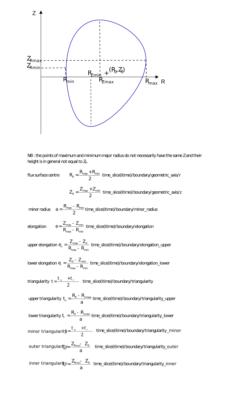
position_control/elongation-structure¶Elongation of the plasma boundary
Elongation of the plasma boundary
Click here for further documentation.
position_control/elongation/reference_nameSTR_0D¶Reference name (e.g. […]
Reference name (e.g. in the native pulse schedule system of the device)
position_control/elongation/reference(:) ⇹mixedFLT_1D¶Reference waveform. […]
Reference waveform. Caution : error bars of the reference/data node are not used in the usual sense, instead they are used to describe the control envelope, with a meaning depending on the chosen envelope_type option.
1 |
Changed in version 3.40.0: Renamed from reference/data
position_control/elongation/reference_typeINT_0D¶Reference type: 0:relative (don’t use for the moment, to be […]
Reference type: 0:relative (don’t use for the moment, to be defined later when segments are introduced in the IDS structure); 1: absolute: the reference time trace is provided in the reference/data node
position_control/elongation/envelope_typeINT_0D¶Envelope type: 0:relative: means that the envelope upper and […]
Envelope type: 0:relative: means that the envelope upper and lower bound values are defined respectively as reference.data * reference.data_error_upper and reference.data * reference.data_error_lower. 1: absolute: the envelope upper and lower bound values are given respectively by reference/data_error_upper and reference/data_error_lower. Lower are upper are taken in the strict mathematical sense, without considering absolute values of the data
position_control/elongation_upper-structure¶Elongation (upper half w.r.t. […]
Elongation (upper half w.r.t. geometric axis) of the plasma boundary
Click here for further documentation.
position_control/elongation_upper/reference_nameSTR_0D¶Reference name (e.g. […]
Reference name (e.g. in the native pulse schedule system of the device)
position_control/elongation_upper/reference(:) ⇹mixedFLT_1D¶Reference waveform. […]
Reference waveform. Caution : error bars of the reference/data node are not used in the usual sense, instead they are used to describe the control envelope, with a meaning depending on the chosen envelope_type option.
1 |
Changed in version 3.40.0: Renamed from reference/data
position_control/elongation_upper/reference_typeINT_0D¶Reference type: 0:relative (don’t use for the moment, to be […]
Reference type: 0:relative (don’t use for the moment, to be defined later when segments are introduced in the IDS structure); 1: absolute: the reference time trace is provided in the reference/data node
position_control/elongation_upper/envelope_typeINT_0D¶Envelope type: 0:relative: means that the envelope upper and […]
Envelope type: 0:relative: means that the envelope upper and lower bound values are defined respectively as reference.data * reference.data_error_upper and reference.data * reference.data_error_lower. 1: absolute: the envelope upper and lower bound values are given respectively by reference/data_error_upper and reference/data_error_lower. Lower are upper are taken in the strict mathematical sense, without considering absolute values of the data
position_control/elongation_lower-structure¶Elongation (lower half w.r.t. […]
Elongation (lower half w.r.t. geometric axis) of the plasma boundary
Click here for further documentation.
position_control/elongation_lower/reference_nameSTR_0D¶Reference name (e.g. […]
Reference name (e.g. in the native pulse schedule system of the device)
position_control/elongation_lower/reference(:) ⇹mixedFLT_1D¶Reference waveform. […]
Reference waveform. Caution : error bars of the reference/data node are not used in the usual sense, instead they are used to describe the control envelope, with a meaning depending on the chosen envelope_type option.
1 |
Changed in version 3.40.0: Renamed from reference/data
position_control/elongation_lower/reference_typeINT_0D¶Reference type: 0:relative (don’t use for the moment, to be […]
Reference type: 0:relative (don’t use for the moment, to be defined later when segments are introduced in the IDS structure); 1: absolute: the reference time trace is provided in the reference/data node
position_control/elongation_lower/envelope_typeINT_0D¶Envelope type: 0:relative: means that the envelope upper and […]
Envelope type: 0:relative: means that the envelope upper and lower bound values are defined respectively as reference.data * reference.data_error_upper and reference.data * reference.data_error_lower. 1: absolute: the envelope upper and lower bound values are given respectively by reference/data_error_upper and reference/data_error_lower. Lower are upper are taken in the strict mathematical sense, without considering absolute values of the data
position_control/triangularity-structure¶Triangularity of the plasma boundary
Triangularity of the plasma boundary
Click here for further documentation.
position_control/triangularity/reference_nameSTR_0D¶Reference name (e.g. […]
Reference name (e.g. in the native pulse schedule system of the device)
position_control/triangularity/reference(:) ⇹mixedFLT_1D¶Reference waveform. […]
Reference waveform. Caution : error bars of the reference/data node are not used in the usual sense, instead they are used to describe the control envelope, with a meaning depending on the chosen envelope_type option.
1 |
Changed in version 3.40.0: Renamed from reference/data
position_control/triangularity/reference_typeINT_0D¶Reference type: 0:relative (don’t use for the moment, to be […]
Reference type: 0:relative (don’t use for the moment, to be defined later when segments are introduced in the IDS structure); 1: absolute: the reference time trace is provided in the reference/data node
position_control/triangularity/envelope_typeINT_0D¶Envelope type: 0:relative: means that the envelope upper and […]
Envelope type: 0:relative: means that the envelope upper and lower bound values are defined respectively as reference.data * reference.data_error_upper and reference.data * reference.data_error_lower. 1: absolute: the envelope upper and lower bound values are given respectively by reference/data_error_upper and reference/data_error_lower. Lower are upper are taken in the strict mathematical sense, without considering absolute values of the data
position_control/triangularity_upper-structure¶Upper triangularity of the plasma boundary
Upper triangularity of the plasma boundary
Click here for further documentation.
position_control/triangularity_upper/reference_nameSTR_0D¶Reference name (e.g. […]
Reference name (e.g. in the native pulse schedule system of the device)
position_control/triangularity_upper/reference(:) ⇹mixedFLT_1D¶Reference waveform. […]
Reference waveform. Caution : error bars of the reference/data node are not used in the usual sense, instead they are used to describe the control envelope, with a meaning depending on the chosen envelope_type option.
1 |
Changed in version 3.40.0: Renamed from reference/data
position_control/triangularity_upper/reference_typeINT_0D¶Reference type: 0:relative (don’t use for the moment, to be […]
Reference type: 0:relative (don’t use for the moment, to be defined later when segments are introduced in the IDS structure); 1: absolute: the reference time trace is provided in the reference/data node
position_control/triangularity_upper/envelope_typeINT_0D¶Envelope type: 0:relative: means that the envelope upper and […]
Envelope type: 0:relative: means that the envelope upper and lower bound values are defined respectively as reference.data * reference.data_error_upper and reference.data * reference.data_error_lower. 1: absolute: the envelope upper and lower bound values are given respectively by reference/data_error_upper and reference/data_error_lower. Lower are upper are taken in the strict mathematical sense, without considering absolute values of the data
position_control/triangularity_lower-structure¶Lower triangularity of the plasma boundary
Lower triangularity of the plasma boundary
Click here for further documentation.
position_control/triangularity_lower/reference_nameSTR_0D¶Reference name (e.g. […]
Reference name (e.g. in the native pulse schedule system of the device)
position_control/triangularity_lower/reference(:) ⇹mixedFLT_1D¶Reference waveform. […]
Reference waveform. Caution : error bars of the reference/data node are not used in the usual sense, instead they are used to describe the control envelope, with a meaning depending on the chosen envelope_type option.
1 |
Changed in version 3.40.0: Renamed from reference/data
position_control/triangularity_lower/reference_typeINT_0D¶Reference type: 0:relative (don’t use for the moment, to be […]
Reference type: 0:relative (don’t use for the moment, to be defined later when segments are introduced in the IDS structure); 1: absolute: the reference time trace is provided in the reference/data node
position_control/triangularity_lower/envelope_typeINT_0D¶Envelope type: 0:relative: means that the envelope upper and […]
Envelope type: 0:relative: means that the envelope upper and lower bound values are defined respectively as reference.data * reference.data_error_upper and reference.data * reference.data_error_lower. 1: absolute: the envelope upper and lower bound values are given respectively by reference/data_error_upper and reference/data_error_lower. Lower are upper are taken in the strict mathematical sense, without considering absolute values of the data
position_control/triangularity_inner-structure¶Inner triangularity of the plasma boundary
Inner triangularity of the plasma boundary
Click here for further documentation.
New in version >3.38.1.
position_control/triangularity_inner/reference_nameSTR_0D¶Reference name (e.g. […]
Reference name (e.g. in the native pulse schedule system of the device)
position_control/triangularity_inner/reference(:) ⇹mixedFLT_1D¶Reference waveform. […]
Reference waveform. Caution : error bars of the reference/data node are not used in the usual sense, instead they are used to describe the control envelope, with a meaning depending on the chosen envelope_type option.
1 |
Changed in version 3.40.0: Renamed from reference/data
position_control/triangularity_inner/reference_typeINT_0D¶Reference type: 0:relative (don’t use for the moment, to be […]
Reference type: 0:relative (don’t use for the moment, to be defined later when segments are introduced in the IDS structure); 1: absolute: the reference time trace is provided in the reference/data node
position_control/triangularity_inner/envelope_typeINT_0D¶Envelope type: 0:relative: means that the envelope upper and […]
Envelope type: 0:relative: means that the envelope upper and lower bound values are defined respectively as reference.data * reference.data_error_upper and reference.data * reference.data_error_lower. 1: absolute: the envelope upper and lower bound values are given respectively by reference/data_error_upper and reference/data_error_lower. Lower are upper are taken in the strict mathematical sense, without considering absolute values of the data
position_control/triangularity_outer-structure¶Outer triangularity of the plasma boundary
Outer triangularity of the plasma boundary
Click here for further documentation.
New in version >3.38.1.
position_control/triangularity_outer/reference_nameSTR_0D¶Reference name (e.g. […]
Reference name (e.g. in the native pulse schedule system of the device)
position_control/triangularity_outer/reference(:) ⇹mixedFLT_1D¶Reference waveform. […]
Reference waveform. Caution : error bars of the reference/data node are not used in the usual sense, instead they are used to describe the control envelope, with a meaning depending on the chosen envelope_type option.
1 |
Changed in version 3.40.0: Renamed from reference/data
position_control/triangularity_outer/reference_typeINT_0D¶Reference type: 0:relative (don’t use for the moment, to be […]
Reference type: 0:relative (don’t use for the moment, to be defined later when segments are introduced in the IDS structure); 1: absolute: the reference time trace is provided in the reference/data node
position_control/triangularity_outer/envelope_typeINT_0D¶Envelope type: 0:relative: means that the envelope upper and […]
Envelope type: 0:relative: means that the envelope upper and lower bound values are defined respectively as reference.data * reference.data_error_upper and reference.data * reference.data_error_lower. 1: absolute: the envelope upper and lower bound values are given respectively by reference/data_error_upper and reference/data_error_lower. Lower are upper are taken in the strict mathematical sense, without considering absolute values of the data
position_control/triangularity_minor-structure¶Minor triangularity of the plasma boundary
Minor triangularity of the plasma boundary
Click here for further documentation.
New in version >3.38.1.
position_control/triangularity_minor/reference_nameSTR_0D¶Reference name (e.g. […]
Reference name (e.g. in the native pulse schedule system of the device)
position_control/triangularity_minor/reference(:) ⇹mixedFLT_1D¶Reference waveform. […]
Reference waveform. Caution : error bars of the reference/data node are not used in the usual sense, instead they are used to describe the control envelope, with a meaning depending on the chosen envelope_type option.
1 |
Changed in version 3.40.0: Renamed from reference/data
position_control/triangularity_minor/reference_typeINT_0D¶Reference type: 0:relative (don’t use for the moment, to be […]
Reference type: 0:relative (don’t use for the moment, to be defined later when segments are introduced in the IDS structure); 1: absolute: the reference time trace is provided in the reference/data node
position_control/triangularity_minor/envelope_typeINT_0D¶Envelope type: 0:relative: means that the envelope upper and […]
Envelope type: 0:relative: means that the envelope upper and lower bound values are defined respectively as reference.data * reference.data_error_upper and reference.data * reference.data_error_lower. 1: absolute: the envelope upper and lower bound values are given respectively by reference/data_error_upper and reference/data_error_lower. Lower are upper are taken in the strict mathematical sense, without considering absolute values of the data
position_control/squareness_upper_outer-structure¶Upper outer squareness of the plasma boundary (definition from […]
Upper outer squareness of the plasma boundary (definition from T. Luce, Plasma Phys. Control. Fusion 55 (2013) 095009)
New in version >3.38.1.
position_control/squareness_upper_outer/reference_nameSTR_0D¶Reference name (e.g. […]
Reference name (e.g. in the native pulse schedule system of the device)
position_control/squareness_upper_outer/reference(:) ⇹mixedFLT_1D¶Reference waveform. […]
Reference waveform. Caution : error bars of the reference/data node are not used in the usual sense, instead they are used to describe the control envelope, with a meaning depending on the chosen envelope_type option.
1 |
Changed in version 3.40.0: Renamed from reference/data
position_control/squareness_upper_outer/reference_typeINT_0D¶Reference type: 0:relative (don’t use for the moment, to be […]
Reference type: 0:relative (don’t use for the moment, to be defined later when segments are introduced in the IDS structure); 1: absolute: the reference time trace is provided in the reference/data node
position_control/squareness_upper_outer/envelope_typeINT_0D¶Envelope type: 0:relative: means that the envelope upper and […]
Envelope type: 0:relative: means that the envelope upper and lower bound values are defined respectively as reference.data * reference.data_error_upper and reference.data * reference.data_error_lower. 1: absolute: the envelope upper and lower bound values are given respectively by reference/data_error_upper and reference/data_error_lower. Lower are upper are taken in the strict mathematical sense, without considering absolute values of the data
position_control/squareness_upper_inner-structure¶Upper inner squareness of the plasma boundary (definition from […]
Upper inner squareness of the plasma boundary (definition from T. Luce, Plasma Phys. Control. Fusion 55 (2013) 095009)
New in version >3.38.1.
position_control/squareness_upper_inner/reference_nameSTR_0D¶Reference name (e.g. […]
Reference name (e.g. in the native pulse schedule system of the device)
position_control/squareness_upper_inner/reference(:) ⇹mixedFLT_1D¶Reference waveform. […]
Reference waveform. Caution : error bars of the reference/data node are not used in the usual sense, instead they are used to describe the control envelope, with a meaning depending on the chosen envelope_type option.
1 |
Changed in version 3.40.0: Renamed from reference/data
position_control/squareness_upper_inner/reference_typeINT_0D¶Reference type: 0:relative (don’t use for the moment, to be […]
Reference type: 0:relative (don’t use for the moment, to be defined later when segments are introduced in the IDS structure); 1: absolute: the reference time trace is provided in the reference/data node
position_control/squareness_upper_inner/envelope_typeINT_0D¶Envelope type: 0:relative: means that the envelope upper and […]
Envelope type: 0:relative: means that the envelope upper and lower bound values are defined respectively as reference.data * reference.data_error_upper and reference.data * reference.data_error_lower. 1: absolute: the envelope upper and lower bound values are given respectively by reference/data_error_upper and reference/data_error_lower. Lower are upper are taken in the strict mathematical sense, without considering absolute values of the data
position_control/squareness_lower_outer-structure¶Lower outer squareness of the plasma boundary (definition from […]
Lower outer squareness of the plasma boundary (definition from T. Luce, Plasma Phys. Control. Fusion 55 (2013) 095009)
New in version >3.38.1.
position_control/squareness_lower_outer/reference_nameSTR_0D¶Reference name (e.g. […]
Reference name (e.g. in the native pulse schedule system of the device)
position_control/squareness_lower_outer/reference(:) ⇹mixedFLT_1D¶Reference waveform. […]
Reference waveform. Caution : error bars of the reference/data node are not used in the usual sense, instead they are used to describe the control envelope, with a meaning depending on the chosen envelope_type option.
1 |
Changed in version 3.40.0: Renamed from reference/data
position_control/squareness_lower_outer/reference_typeINT_0D¶Reference type: 0:relative (don’t use for the moment, to be […]
Reference type: 0:relative (don’t use for the moment, to be defined later when segments are introduced in the IDS structure); 1: absolute: the reference time trace is provided in the reference/data node
position_control/squareness_lower_outer/envelope_typeINT_0D¶Envelope type: 0:relative: means that the envelope upper and […]
Envelope type: 0:relative: means that the envelope upper and lower bound values are defined respectively as reference.data * reference.data_error_upper and reference.data * reference.data_error_lower. 1: absolute: the envelope upper and lower bound values are given respectively by reference/data_error_upper and reference/data_error_lower. Lower are upper are taken in the strict mathematical sense, without considering absolute values of the data
position_control/squareness_lower_inner-structure¶Lower inner squareness of the plasma boundary (definition from […]
Lower inner squareness of the plasma boundary (definition from T. Luce, Plasma Phys. Control. Fusion 55 (2013) 095009)
New in version >3.38.1.
position_control/squareness_lower_inner/reference_nameSTR_0D¶Reference name (e.g. […]
Reference name (e.g. in the native pulse schedule system of the device)
position_control/squareness_lower_inner/reference(:) ⇹mixedFLT_1D¶Reference waveform. […]
Reference waveform. Caution : error bars of the reference/data node are not used in the usual sense, instead they are used to describe the control envelope, with a meaning depending on the chosen envelope_type option.
1 |
Changed in version 3.40.0: Renamed from reference/data
position_control/squareness_lower_inner/reference_typeINT_0D¶Reference type: 0:relative (don’t use for the moment, to be […]
Reference type: 0:relative (don’t use for the moment, to be defined later when segments are introduced in the IDS structure); 1: absolute: the reference time trace is provided in the reference/data node
position_control/squareness_lower_inner/envelope_typeINT_0D¶Envelope type: 0:relative: means that the envelope upper and […]
Envelope type: 0:relative: means that the envelope upper and lower bound values are defined respectively as reference.data * reference.data_error_upper and reference.data * reference.data_error_lower. 1: absolute: the envelope upper and lower bound values are given respectively by reference/data_error_upper and reference/data_error_lower. Lower are upper are taken in the strict mathematical sense, without considering absolute values of the data
position_control/x_point(i1)AoS¶Array of X-points, for each of them the RZ position is given
Array of X-points, for each of them the RZ position is given
Maximum occurrences (MDS+ backend only): 2
1 |
|
position_control/x_point(i1)/rmstructure¶Major radius
Major radius
position_control/x_point(i1)/r/reference_nameSTR_0D¶Reference name (e.g. […]
Reference name (e.g. in the native pulse schedule system of the device)
position_control/x_point(i1)/r/reference(:) ⇹mixedFLT_1D¶Reference waveform. […]
Reference waveform. Caution : error bars of the reference/data node are not used in the usual sense, instead they are used to describe the control envelope, with a meaning depending on the chosen envelope_type option.
1 |
Changed in version 3.40.0: Renamed from reference/data
position_control/x_point(i1)/r/reference_typeINT_0D¶Reference type: 0:relative (don’t use for the moment, to be […]
Reference type: 0:relative (don’t use for the moment, to be defined later when segments are introduced in the IDS structure); 1: absolute: the reference time trace is provided in the reference/data node
position_control/x_point(i1)/r/envelope_typeINT_0D¶Envelope type: 0:relative: means that the envelope upper and […]
Envelope type: 0:relative: means that the envelope upper and lower bound values are defined respectively as reference.data * reference.data_error_upper and reference.data * reference.data_error_lower. 1: absolute: the envelope upper and lower bound values are given respectively by reference/data_error_upper and reference/data_error_lower. Lower are upper are taken in the strict mathematical sense, without considering absolute values of the data
position_control/x_point(i1)/zmstructure¶Height
Height
position_control/x_point(i1)/z/reference_nameSTR_0D¶Reference name (e.g. […]
Reference name (e.g. in the native pulse schedule system of the device)
position_control/x_point(i1)/z/reference(:) ⇹mixedFLT_1D¶Reference waveform. […]
Reference waveform. Caution : error bars of the reference/data node are not used in the usual sense, instead they are used to describe the control envelope, with a meaning depending on the chosen envelope_type option.
1 |
Changed in version 3.40.0: Renamed from reference/data
position_control/x_point(i1)/z/reference_typeINT_0D¶Reference type: 0:relative (don’t use for the moment, to be […]
Reference type: 0:relative (don’t use for the moment, to be defined later when segments are introduced in the IDS structure); 1: absolute: the reference time trace is provided in the reference/data node
position_control/x_point(i1)/z/envelope_typeINT_0D¶Envelope type: 0:relative: means that the envelope upper and […]
Envelope type: 0:relative: means that the envelope upper and lower bound values are defined respectively as reference.data * reference.data_error_upper and reference.data * reference.data_error_lower. 1: absolute: the envelope upper and lower bound values are given respectively by reference/data_error_upper and reference/data_error_lower. Lower are upper are taken in the strict mathematical sense, without considering absolute values of the data
position_control/strike_point(i1)AoS¶Array of strike points, for each of them the RZ position is given
Array of strike points, for each of them the RZ position is given
Maximum occurrences (MDS+ backend only): 4
1 |
|
position_control/strike_point(i1)/rmstructure¶Major radius
Major radius
position_control/strike_point(i1)/r/reference_nameSTR_0D¶Reference name (e.g. […]
Reference name (e.g. in the native pulse schedule system of the device)
position_control/strike_point(i1)/r/reference(:) ⇹mixedFLT_1D¶Reference waveform. […]
Reference waveform. Caution : error bars of the reference/data node are not used in the usual sense, instead they are used to describe the control envelope, with a meaning depending on the chosen envelope_type option.
1 |
Changed in version 3.40.0: Renamed from reference/data
position_control/strike_point(i1)/r/reference_typeINT_0D¶Reference type: 0:relative (don’t use for the moment, to be […]
Reference type: 0:relative (don’t use for the moment, to be defined later when segments are introduced in the IDS structure); 1: absolute: the reference time trace is provided in the reference/data node
position_control/strike_point(i1)/r/envelope_typeINT_0D¶Envelope type: 0:relative: means that the envelope upper and […]
Envelope type: 0:relative: means that the envelope upper and lower bound values are defined respectively as reference.data * reference.data_error_upper and reference.data * reference.data_error_lower. 1: absolute: the envelope upper and lower bound values are given respectively by reference/data_error_upper and reference/data_error_lower. Lower are upper are taken in the strict mathematical sense, without considering absolute values of the data
position_control/strike_point(i1)/zmstructure¶Height
Height
position_control/strike_point(i1)/z/reference_nameSTR_0D¶Reference name (e.g. […]
Reference name (e.g. in the native pulse schedule system of the device)
position_control/strike_point(i1)/z/reference(:) ⇹mixedFLT_1D¶Reference waveform. […]
Reference waveform. Caution : error bars of the reference/data node are not used in the usual sense, instead they are used to describe the control envelope, with a meaning depending on the chosen envelope_type option.
1 |
Changed in version 3.40.0: Renamed from reference/data
position_control/strike_point(i1)/z/reference_typeINT_0D¶Reference type: 0:relative (don’t use for the moment, to be […]
Reference type: 0:relative (don’t use for the moment, to be defined later when segments are introduced in the IDS structure); 1: absolute: the reference time trace is provided in the reference/data node
position_control/strike_point(i1)/z/envelope_typeINT_0D¶Envelope type: 0:relative: means that the envelope upper and […]
Envelope type: 0:relative: means that the envelope upper and lower bound values are defined respectively as reference.data * reference.data_error_upper and reference.data * reference.data_error_lower. 1: absolute: the envelope upper and lower bound values are given respectively by reference/data_error_upper and reference/data_error_lower. Lower are upper are taken in the strict mathematical sense, without considering absolute values of the data
position_control/active_limiter_pointstructure¶RZ position of the active limiter point (point of the plasma […]
RZ position of the active limiter point (point of the plasma boundary in contact with the limiter)
position_control/active_limiter_point/rmstructure¶Major radius
Major radius
position_control/active_limiter_point/r/reference_nameSTR_0D¶Reference name (e.g. […]
Reference name (e.g. in the native pulse schedule system of the device)
position_control/active_limiter_point/r/reference(:) ⇹mixedFLT_1D¶Reference waveform. […]
Reference waveform. Caution : error bars of the reference/data node are not used in the usual sense, instead they are used to describe the control envelope, with a meaning depending on the chosen envelope_type option.
1 |
Changed in version 3.40.0: Renamed from reference/data
position_control/active_limiter_point/r/reference_typeINT_0D¶Reference type: 0:relative (don’t use for the moment, to be […]
Reference type: 0:relative (don’t use for the moment, to be defined later when segments are introduced in the IDS structure); 1: absolute: the reference time trace is provided in the reference/data node
position_control/active_limiter_point/r/envelope_typeINT_0D¶Envelope type: 0:relative: means that the envelope upper and […]
Envelope type: 0:relative: means that the envelope upper and lower bound values are defined respectively as reference.data * reference.data_error_upper and reference.data * reference.data_error_lower. 1: absolute: the envelope upper and lower bound values are given respectively by reference/data_error_upper and reference/data_error_lower. Lower are upper are taken in the strict mathematical sense, without considering absolute values of the data
position_control/active_limiter_point/zmstructure¶Height
Height
position_control/active_limiter_point/z/reference_nameSTR_0D¶Reference name (e.g. […]
Reference name (e.g. in the native pulse schedule system of the device)
position_control/active_limiter_point/z/reference(:) ⇹mixedFLT_1D¶Reference waveform. […]
Reference waveform. Caution : error bars of the reference/data node are not used in the usual sense, instead they are used to describe the control envelope, with a meaning depending on the chosen envelope_type option.
1 |
Changed in version 3.40.0: Renamed from reference/data
position_control/active_limiter_point/z/reference_typeINT_0D¶Reference type: 0:relative (don’t use for the moment, to be […]
Reference type: 0:relative (don’t use for the moment, to be defined later when segments are introduced in the IDS structure); 1: absolute: the reference time trace is provided in the reference/data node
position_control/active_limiter_point/z/envelope_typeINT_0D¶Envelope type: 0:relative: means that the envelope upper and […]
Envelope type: 0:relative: means that the envelope upper and lower bound values are defined respectively as reference.data * reference.data_error_upper and reference.data * reference.data_error_lower. 1: absolute: the envelope upper and lower bound values are given respectively by reference/data_error_upper and reference/data_error_lower. Lower are upper are taken in the strict mathematical sense, without considering absolute values of the data
position_control/boundary_outline(i1)AoS¶Set of (R,Z) points defining the outline of the plasma boundary
Set of (R,Z) points defining the outline of the plasma boundary
Maximum occurrences (MDS+ backend only): 301
1 |
|
position_control/boundary_outline(i1)/rmstructure¶Major radius
Major radius
position_control/boundary_outline(i1)/r/reference_nameSTR_0D¶Reference name (e.g. […]
Reference name (e.g. in the native pulse schedule system of the device)
position_control/boundary_outline(i1)/r/reference(:) ⇹mixedFLT_1D¶Reference waveform. […]
Reference waveform. Caution : error bars of the reference/data node are not used in the usual sense, instead they are used to describe the control envelope, with a meaning depending on the chosen envelope_type option.
1 |
Changed in version 3.40.0: Renamed from reference/data
position_control/boundary_outline(i1)/r/reference_typeINT_0D¶Reference type: 0:relative (don’t use for the moment, to be […]
Reference type: 0:relative (don’t use for the moment, to be defined later when segments are introduced in the IDS structure); 1: absolute: the reference time trace is provided in the reference/data node
position_control/boundary_outline(i1)/r/envelope_typeINT_0D¶Envelope type: 0:relative: means that the envelope upper and […]
Envelope type: 0:relative: means that the envelope upper and lower bound values are defined respectively as reference.data * reference.data_error_upper and reference.data * reference.data_error_lower. 1: absolute: the envelope upper and lower bound values are given respectively by reference/data_error_upper and reference/data_error_lower. Lower are upper are taken in the strict mathematical sense, without considering absolute values of the data
position_control/boundary_outline(i1)/zmstructure¶Height
Height
position_control/boundary_outline(i1)/z/reference_nameSTR_0D¶Reference name (e.g. […]
Reference name (e.g. in the native pulse schedule system of the device)
position_control/boundary_outline(i1)/z/reference(:) ⇹mixedFLT_1D¶Reference waveform. […]
Reference waveform. Caution : error bars of the reference/data node are not used in the usual sense, instead they are used to describe the control envelope, with a meaning depending on the chosen envelope_type option.
1 |
Changed in version 3.40.0: Renamed from reference/data
position_control/boundary_outline(i1)/z/reference_typeINT_0D¶Reference type: 0:relative (don’t use for the moment, to be […]
Reference type: 0:relative (don’t use for the moment, to be defined later when segments are introduced in the IDS structure); 1: absolute: the reference time trace is provided in the reference/data node
position_control/boundary_outline(i1)/z/envelope_typeINT_0D¶Envelope type: 0:relative: means that the envelope upper and […]
Envelope type: 0:relative: means that the envelope upper and lower bound values are defined respectively as reference.data * reference.data_error_upper and reference.data * reference.data_error_lower. 1: absolute: the envelope upper and lower bound values are given respectively by reference/data_error_upper and reference/data_error_lower. Lower are upper are taken in the strict mathematical sense, without considering absolute values of the data
position_control/z_r_maxmstructure¶Height of the separatrix point of maximum major radius
Height of the separatrix point of maximum major radius
New in version >3.38.1.
position_control/z_r_max/reference_nameSTR_0D¶Reference name (e.g. […]
Reference name (e.g. in the native pulse schedule system of the device)
position_control/z_r_max/reference(:) ⇹mixedFLT_1D¶Reference waveform. […]
Reference waveform. Caution : error bars of the reference/data node are not used in the usual sense, instead they are used to describe the control envelope, with a meaning depending on the chosen envelope_type option.
1 |
Changed in version 3.40.0: Renamed from reference/data
position_control/z_r_max/reference_typeINT_0D¶Reference type: 0:relative (don’t use for the moment, to be […]
Reference type: 0:relative (don’t use for the moment, to be defined later when segments are introduced in the IDS structure); 1: absolute: the reference time trace is provided in the reference/data node
position_control/z_r_max/envelope_typeINT_0D¶Envelope type: 0:relative: means that the envelope upper and […]
Envelope type: 0:relative: means that the envelope upper and lower bound values are defined respectively as reference.data * reference.data_error_upper and reference.data * reference.data_error_lower. 1: absolute: the envelope upper and lower bound values are given respectively by reference/data_error_upper and reference/data_error_lower. Lower are upper are taken in the strict mathematical sense, without considering absolute values of the data
position_control/z_r_minmstructure¶Height of the separatrix point of minimum major radius
Height of the separatrix point of minimum major radius
New in version >3.38.1.
position_control/z_r_min/reference_nameSTR_0D¶Reference name (e.g. […]
Reference name (e.g. in the native pulse schedule system of the device)
position_control/z_r_min/reference(:) ⇹mixedFLT_1D¶Reference waveform. […]
Reference waveform. Caution : error bars of the reference/data node are not used in the usual sense, instead they are used to describe the control envelope, with a meaning depending on the chosen envelope_type option.
1 |
Changed in version 3.40.0: Renamed from reference/data
position_control/z_r_min/reference_typeINT_0D¶Reference type: 0:relative (don’t use for the moment, to be […]
Reference type: 0:relative (don’t use for the moment, to be defined later when segments are introduced in the IDS structure); 1: absolute: the reference time trace is provided in the reference/data node
position_control/z_r_min/envelope_typeINT_0D¶Envelope type: 0:relative: means that the envelope upper and […]
Envelope type: 0:relative: means that the envelope upper and lower bound values are defined respectively as reference.data * reference.data_error_upper and reference.data * reference.data_error_lower. 1: absolute: the envelope upper and lower bound values are given respectively by reference/data_error_upper and reference/data_error_lower. Lower are upper are taken in the strict mathematical sense, without considering absolute values of the data
position_control/gap(i1)AoS¶Set of gaps, defined by a reference point and a direction.
Set of gaps, defined by a reference point and a direction.
Maximum occurrences (MDS+ backend only): 51
1 |
|
position_control/gap(i1)/r ⇹mFLT_0D¶Major radius of the reference point
Major radius of the reference point
position_control/gap(i1)/angle ⇹radFLT_0D¶Angle between the direction in which the gap is measured (in […]
Angle between the direction in which the gap is measured (in the poloidal cross-section) and the horizontal axis.
position_control/gap(i1)/valuemstructure¶Value of the gap, i.e. […]
Value of the gap, i.e. distance between the reference point and the separatrix along the gap direction
position_control/gap(i1)/value/reference_nameSTR_0D¶Reference name (e.g. […]
Reference name (e.g. in the native pulse schedule system of the device)
position_control/gap(i1)/value/reference(:) ⇹mixedFLT_1D¶Reference waveform. […]
Reference waveform. Caution : error bars of the reference/data node are not used in the usual sense, instead they are used to describe the control envelope, with a meaning depending on the chosen envelope_type option.
1 |
Changed in version 3.40.0: Renamed from reference/data
position_control/gap(i1)/value/reference_typeINT_0D¶Reference type: 0:relative (don’t use for the moment, to be […]
Reference type: 0:relative (don’t use for the moment, to be defined later when segments are introduced in the IDS structure); 1: absolute: the reference time trace is provided in the reference/data node
position_control/gap(i1)/value/envelope_typeINT_0D¶Envelope type: 0:relative: means that the envelope upper and […]
Envelope type: 0:relative: means that the envelope upper and lower bound values are defined respectively as reference.data * reference.data_error_upper and reference.data * reference.data_error_lower. 1: absolute: the envelope upper and lower bound values are given respectively by reference/data_error_upper and reference/data_error_lower. Lower are upper are taken in the strict mathematical sense, without considering absolute values of the data
position_control/current_centroidstructure¶RZ position of the current centroid
RZ position of the current centroid
New in version >3.39.0.
position_control/current_centroid/rmstructure¶Major radius
Major radius
position_control/current_centroid/r/reference_nameSTR_0D¶Reference name (e.g. […]
Reference name (e.g. in the native pulse schedule system of the device)
position_control/current_centroid/r/reference(:) ⇹mixedFLT_1D¶Reference waveform. […]
Reference waveform. Caution : error bars of the reference/data node are not used in the usual sense, instead they are used to describe the control envelope, with a meaning depending on the chosen envelope_type option.
1 |
Changed in version 3.40.0: Renamed from reference/data
position_control/current_centroid/r/reference_typeINT_0D¶Reference type: 0:relative (don’t use for the moment, to be […]
Reference type: 0:relative (don’t use for the moment, to be defined later when segments are introduced in the IDS structure); 1: absolute: the reference time trace is provided in the reference/data node
position_control/current_centroid/r/envelope_typeINT_0D¶Envelope type: 0:relative: means that the envelope upper and […]
Envelope type: 0:relative: means that the envelope upper and lower bound values are defined respectively as reference.data * reference.data_error_upper and reference.data * reference.data_error_lower. 1: absolute: the envelope upper and lower bound values are given respectively by reference/data_error_upper and reference/data_error_lower. Lower are upper are taken in the strict mathematical sense, without considering absolute values of the data
position_control/current_centroid/zmstructure¶Height
Height
position_control/current_centroid/z/reference_nameSTR_0D¶Reference name (e.g. […]
Reference name (e.g. in the native pulse schedule system of the device)
position_control/current_centroid/z/reference(:) ⇹mixedFLT_1D¶Reference waveform. […]
Reference waveform. Caution : error bars of the reference/data node are not used in the usual sense, instead they are used to describe the control envelope, with a meaning depending on the chosen envelope_type option.
1 |
Changed in version 3.40.0: Renamed from reference/data
position_control/current_centroid/z/reference_typeINT_0D¶Reference type: 0:relative (don’t use for the moment, to be […]
Reference type: 0:relative (don’t use for the moment, to be defined later when segments are introduced in the IDS structure); 1: absolute: the reference time trace is provided in the reference/data node
position_control/current_centroid/z/envelope_typeINT_0D¶Envelope type: 0:relative: means that the envelope upper and […]
Envelope type: 0:relative: means that the envelope upper and lower bound values are defined respectively as reference.data * reference.data_error_upper and reference.data * reference.data_error_lower. 1: absolute: the envelope upper and lower bound values are given respectively by reference/data_error_upper and reference/data_error_lower. Lower are upper are taken in the strict mathematical sense, without considering absolute values of the data
position_control/mode(:)INT_1D¶Control mode (operation mode and/or settings used by the controller)
Control mode (operation mode and/or settings used by the controller)
1 |
Changed in version 3.40.0: Renamed from mode/data
tfstructure¶Toroidal field references
Toroidal field references
tf/b_field_tor_vacuum_rT.mstructure¶Vacuum field times major radius in the toroidal field magnet. […]
Vacuum field times major radius in the toroidal field magnet. Positive sign means anti-clockwise when viewed from above
tf/b_field_tor_vacuum_r/reference_nameSTR_0D¶Reference name (e.g. […]
Reference name (e.g. in the native pulse schedule system of the device)
tf/b_field_tor_vacuum_r/reference(:) ⇹mixedFLT_1D¶Reference waveform. […]
Reference waveform. Caution : error bars of the reference/data node are not used in the usual sense, instead they are used to describe the control envelope, with a meaning depending on the chosen envelope_type option.
1 |
Changed in version 3.40.0: Renamed from reference/data
tf/b_field_tor_vacuum_r/reference_typeINT_0D¶Reference type: 0:relative (don’t use for the moment, to be […]
Reference type: 0:relative (don’t use for the moment, to be defined later when segments are introduced in the IDS structure); 1: absolute: the reference time trace is provided in the reference/data node
tf/b_field_tor_vacuum_r/envelope_typeINT_0D¶Envelope type: 0:relative: means that the envelope upper and […]
Envelope type: 0:relative: means that the envelope upper and lower bound values are defined respectively as reference.data * reference.data_error_upper and reference.data * reference.data_error_lower. 1: absolute: the envelope upper and lower bound values are given respectively by reference/data_error_upper and reference/data_error_lower. Lower are upper are taken in the strict mathematical sense, without considering absolute values of the data
tf/mode(:)INT_1D¶Control mode (operation mode and/or settings used by the controller)
Control mode (operation mode and/or settings used by the controller)
1 |
Changed in version 3.40.0: Renamed from mode/data